
List of Composite Bridge Design Standards: [Show]
• EN 1991-1-1: Actions on Structures - General Actions
• EN 1991-1-4: Actions on Structures - Wind Actions
• EN 1991-1-5: Actions on Structures - Thermal Actions
• EN 1991-1-7: Actions on Structures - Accidental Actions
• EN 1991-2: Actions on Structures - Traffic Loads on Bridges
• EN 1994-1-1: Design of Composite Steel and Concrete Structures - General
Rules
• EN 1994-2: Design of Composite Steel and Concrete Structures - Bridges
• Each document is accompanied by a National Annex
British Standards
• BS 5400: Part 2: Specification for Loads
• BS 5400: Part 3: Code of Practice for the Design of Steel Bridges
• BS 5400: Part 4: Code of Practice for the Design of Concrete Bridges
• BS 5400: Part 5: Code of Practice for the Design of Composite Bridges
• BS 8500: Concrete - Complementary British Standard to BS EN 206-1
• BS 8666: Specification for scheduling, dimensioning, bending and cutting of
steel reinforcement for concrete
• BS EN 10025 Parts 1 to 6: Hot rolled products of structural steels
Design Manual for Roads and Bridges
• BD13: Design of Steel Bridges
• BD16: Design of Composite Bridges
• BD24: Design of Concrete Bridges
• BD28: Early Thermal Cracking of Concrete
• BD37: Loads for Highway Bridges
• BD57 and BA57: Design for Durability
Technical Papers
• CIRIA Report C660 - Early-age thermal crack control in concrete.
Composite Decks
Composite
Construction in bridge decks usually refers to the interaction between
insitu reinforced concrete and structural steel.
Three main economic advantages of composite construction are :
For a given span and loading system a smaller depth of beam can be used than for a concrete beam solution, which leads to economies in the approach embankments.
-
The cross-sectional area of the steel top flange can be reduced because the concrete can be considered as part of it.
-
Transverse stiffening for the top compression flange of the steel beam can be reduced because the restraint against buckling is provided by the concrete deck.
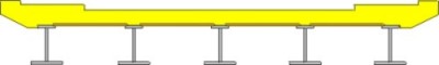
Typical Composite Deck
Construction Methods
It is possible to influence the load carried by a composite
deck section in a number of ways during the erection of a bridge.
By propping the steel beams while the deck slab is cast and until it has
gained strength, then the composite section can be considered to take
the whole of the dead load. This method appears attractive but is seldom
used since propping can be difficult and usually costly.
With continuous spans the concrete slab will crack in the hogging regions
and only the steel reinforcement will be effective in the flexural resistance,
unless the concrete is prestressed.
Generally the concrete deck is 220mm to 250mm thick with beams or plate
girders between 2.5m and 3.5m spacing and depths between span/20 and span/30.
Composite action is developed by the transfer of horizontal shear forces
between the concrete deck and steel via shear studs which are welded to
the steel girder. Typical types of connectors are shown below, the stud connector being the most commonly used.
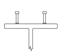
Stud Connector
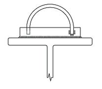
Bar Connector
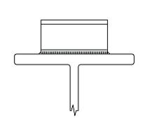
Channel Connector
Bridge Components | Choice of Deck

David Childs
B.Sc, C.Eng, MICE
Last Updated: 28/01/2020