
List of Abutment Design Standards: [Show]
• EN 1991-1-1: Actions on Structures - General Actions
• EN 1991-1-5: Actions on Structures - Thermal Actions
• EN 1991-2: Actions on Structures - Traffic Loads on Bridges
• Each document is accompanied by a National Annex
British Standards
• BS 5400: Part 2: Specification for Loads
Design Manual for Roads and Bridges
• BA26: Expansion Joints for Use in Highway Bridge Decks
• BA42: The Design of Integral Bridges
• BA57 & BD57: Design for Durability
• BD33: Expansion Joints for Use in Highway Bridge Decks
• BD37: Loads for Highway Bridges
Technical Papers
• SR 479 Bridge Temperature for Setting Bearings and Expansion Joints.
By M.Emerson of TRRL
Choice of Deck Joint
Current practice is to make decks integral with the abutments.
The objective is to avoid the use of joints over abutments and piers.
Expansion joints are prone to leak and allow the ingress of de-icing salts into the bridge deck and substructure.
In general all bridges are made continuous over intermediate supports and decks under 60 metres long with skews not exceeding 30° are made integral with their abutments.
Where it is intended not to use road salts, or the deck and substructure have been designed to incorporate deck joints then the following guidance is given in BD 33/94 for the range of movements that can be accommodated by the various joint types:
JOINT TYPE
TOTAL ACCEPTABLE
LONGITUDINAL
MOVEMENT
Min
(mm)
Max
(mm)
MAXIMUM ACCEPTABLE
VERTICAL MOVEMENT
BETWEEN TWO SIDES
OF JOINT (mm)
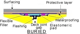
1. Buried joint under
continuous surfacing.
5
20
1.3
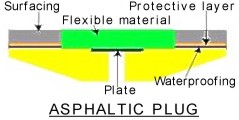
2. Asphaltic Plug joint.
5
40
3
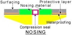
3. Nosing joint with
poured sealant.
5
12
3
4. Nosing with preformed
compression seal.
5
40
3
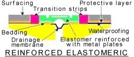
5. Reinforced Elastomeric.
5
*
3
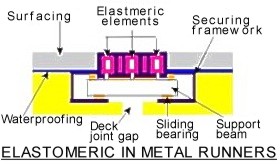
6. Elastomeric in metal
runners.
5
*
3
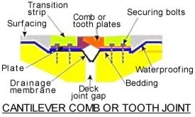
7. Cantilever comb or
tooth joint.
25
*
3
The minimum of the range is given to indicate when the type of joint may not be economical.
* Maximum value varies according to manufacturer or type.
Thermal Movements
BS 5400 Part 2 Chapter 5.4 specifies maximum and minimum effective bridge temperatures which have to be accommodated in the bridge structure.
The width of joint between the end of the deck and the abutment is set during construction of the bridge; usually when the concrete curtain wall is cast.
The maximum expansion of the deck is therefore determined from the minimum effective temperature at which the curtain wall is allowed to to be cast; usually 2°C.
Hence if a maximum effective temperature of 40°C is calculated from BS 5400 Part 2 then a joint width will have to be provided at the end of the deck to allow for an expansion caused by a temperature increase of (40-2)=38°C.
The maximum contraction of the deck is determined in a similar manner, but using a nominal effective temperature at which the joint is set.
Having determined the range of movement at the joint then the type of joint can be specified. The nominal effective temperature used in the calculations will also have to be specified to enable the correct adjustments to be made on site when the joints are set.
Joint Manufacturers
An overview of the various types of bridge joints, together with a list of suppliers can be obtained from the Bridge Joint Association.

David Childs
B.Sc, C.Eng, MICE
Last Updated: 28/01/2020