
List of Abutment Design Standards: [Show]
• EN 1991-1-1: Actions on Structures - General Actions
• EN 1991-1-7: Actions on Structures - Accidental Actions
• EN 1991-2: Actions on Structures - Traffic Loads on Bridges
• EN 1992-1-1: Design of Concrete Structures - General Rules
• EN 1992-2: Design of Concrete Structures - Bridges
• EN 1993-5: Design of Steel Structures - Piling
• EN 1997-1: Geotechnical Design - General Rules
• EN 1998-2: Design of Structures for Earthquake Resistance - Bridges
• EN 1998-5: Design of Structures for Earthquake Resistance - Geotechnical
Aspects
• Each document is accompanied by a National Annex
British Standards
• BS 5400: Part 2: Specification for Loads
• BS 5400: Part 4: Code of Practice for the Design of Concrete Bridges
• BS 8002: Code of Practice for Earth Retaining Structures
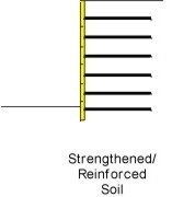
• BS 8006: Strengthened/Reinforced Soils and Other Fills
• BS 8500: Concrete - Complementary British Standard to BS EN 206-1
• BS 8666: Specification for scheduling, dimensioning, bending and cutting of
steel reinforcement for concrete
Design Manual for Roads and Bridges
• BD30: Backfilled Retaining Walls and Bridge Abutments
• BD37: Loads for Highway Bridges
• BA41: The Design and Appearance of Bridges
• BD42: Design of Embedded Retaining Walls and Bridge Abutments
• BD57 and BA57: Design for Durability
• BD68: Crib Retaining Walls
• BD70: Strengthened/Reinforced Soils and Other Fills for Retaining Walls
and Bridge Abutments
Technical Papers
• CIRIA Report C660 - Early-age thermal crack control in concrete.
Choice of Wing Wall
Wing walls are essentially retaining walls adjacent to the abutment. The walls can be independent or integral with the abutment wall.
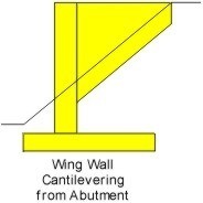
Providing the bridge skew angle is small (less than 20°), and the cutting/embankment slopes are reasonably steep (about 1 in 2), then the wing wall cantilevering from the abutment wall is likely to give the most economical solution.
Splayed wing walls can provide even more of an economy in material costs but the detailing and fixing of the steel reinforcement is more complicated than the conventional wall.
Design Considerations
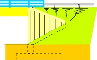
Loads effects to be considered on the rear of the wall are:
Earth pressures from the backfill material.
Surcharge from live loading or compacting plant.
Hydraulic loads from saturated soil conditions.
The stability of the wall is generally designed to resist 'active' earth pressures (Ka); whilst the structural elements are designed to resist 'at rest' earth pressures (Ko). The concept is that 'at rest' pressures are developed initially and the structural elements should be designed to accommodate these loads without failure. The loads will however reduce to 'active' pressure when the wall moves, either by rotating or sliding. Consequently the wall will stabilise if it moves under 'at rest' pressures providing it is designed to resist 'active' earth pressures.
Geometry for splayed wing walls
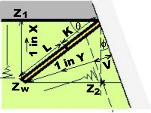
Plan on Wing Wall
X = slope to road under bridge
Y = slope from road over bridge
L = length of sloping wall
K = length of horizontal wall
V = verge width to end of wall
Z1 = level at bottom of embankment
Z2 = level at back of verge on road over bridge
Zw = ground level at end of wall
θ = angle of wall to road under bridge
φ = skew angle ( -ve if < 90°)
Zw = Z1 + 1/x [(L+K)Sinθ]
Zw = Z2 - [(L+K) Cosθ +
(L+K) SinθTanφ - V/Cosφ ] Cosφ / Y
L + K = [ X Y (Z2 - Z1) + V X ] / [ X Cos (θ - φ ) + Y Sinθ] ..................eqn.(1)
For minimum length of wall dL/dθ = 0
ie. Tanθ = Tanφ + Y / X Cosφ
For known lengths of wall (L+K) two values of θ can be obtained from eqn.(1).
From eqn.(1) -(A+B)Tan2(θ/2) + 2(C+Y)Tan(θ/2) + (B-A) = 0
Where A = [XY(Z2 - Z1) + VX] / [L + K] , B = X Cosφ , and C = X Sinφ
Example
Wall
Z1
Z2
V
X
Y
φ
Level
at
top of
wall
(L+K)
Max
&
Min
θ
θ
Zw
Kmax
N/E
56.6
63.6
2.2
2.0
2.0
10.5
63.0
11.0
68.1
to
32.4
32.5
59.6
4.1
S/E
56.9
64.2
2.0
2.0
2.0
-27.0
63.6
15.9
31.5
31.5
61.1
10.8
S/W
57.2
64.4
0.8
2.6
2.0
27.7
63.8
12.2
89.3
to
18.5
30.0
59.6
3.8
Minimum Lengths :-
N/E Wall : L+K = 10.437 @ θ = 50.25°
S/E Wall : L+K = 15.889 @ θ = 31.5°
S/W Wall : L+K = 9.996 @ θ = 54.37°

David Childs
B.Sc, C.Eng, MICE
Last Updated: 28/01/2020