
HA and HB Type Loading
History
The first standard vehicle load for highway bridges in the UK was introduced in 1922.
British Standards introduced a traffic live load requirement in BS 153 Part 3 in 1923, which was later revised in 1925 and 1937.
The Type HA uniformly distibuted loading was introduced in 1945 and the concept of a Type HA and HB load was included in the 1954 edition of BS 153: Part 3A.
In 1961 the HB load was specified in terms of units and varied depending on the class of road, with 45 units required for Motorways and Trunk Roads and 37.5 units for class i and class ii roads.
A requirement for all public roads to be designed for at least 30 units of HB was introduced in 1973.
HA Loading
BD 37/01 Appendix A of the Design Manual for Roads and Bridges says that Type HA loading is the normal design loading for Great Britain and adequately covers the effects of all permitted normal vehicles other than those used for abnormal indivisible loads.
Normal vehicles are governed by the Road Vehicles (Authorised Weight) Regulations 1998, referred to as the AW Vehicles and cover vehicles up to 44 tonne gross vehicle weight.
Loads from these AW vehicles are represented by a Uniformly Distributed Load and a Knife Edge Load. The loading has been enhanced to cover:
i) impact load (caused when wheels 'bounce' i.e. when striking potholes or uneven expansion joints).
ii) overloading
iii) Lateral bunching (more than one vehicle occupying the width of a lane).
The magnitude of the Uniformly Distributed Load is dependent on the loaded length as determined from the influence line for the member under consideration. For simply supported single span decks this usually relates to the span of the deck.
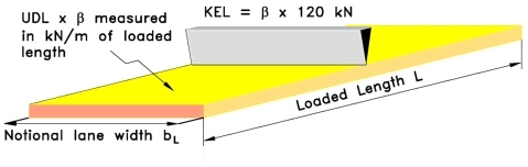
HA UDL+KEL loading on one notional lane.
The UDL (W kN/m) is multiplied by a lane factor β to obtain the value to be applied to each notional lane. If the UDL is required in kN/m2 then W will need to be divided by the notional lane width bL.
The knife edge load (KEL) is also multiplied by the lane factor β. The KEL may be positioned anywhere along the loaded length in order to obtain the worst effect in the member being considered.
A single wheel load of 100 kN also needs to be considered as an alternative to the UDL and KEL as part of the HA loading design. The wheel load can produce more severe effects than the UDL+KEL on short span members.
HB Loading
BD 37/01 Appendix A of the Design Manual for Roads and Bridges says that Type HB loading requirements derive from the nature of exceptional industrial loads (e.g. electrical transformers, generators, pressure vessels, machine presses, etc.) likely to use the roads in the area.
The vehicle load is represented by a four axled vehicle with four wheels equally spaced on each axle. The load on each axle is defined by a number of units which is dependant on the class of road and is specified in BD 37/01 Chapter 4 as follows:
Motorways and trunk roads require 45 units, Principal roads require 37.5 units and other public roads require 30 units.
One unit of HB is equal to 10kN per axle. There are five HB vehicles to check although most vehicles can be discounted by inspection. The spacing between the inner two axles of the vehicle has five diffent values which produces the range of HB vehicle to consider.
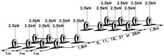
1 unit of HB loading.
Only one HB vehicle is considered to load any one superstructure. The vehicle is positioned within one notional lane or straddles two notional lanes in order to obtain the worst effect on the member. HA loading is placed in any remaing lane not occupied by the HB vehicle. Also, if the deck is long enough, the HA UDL only is placed in the lanes occupied by the HB vehicle, but is omitted from the length of lane within 25m from the front and back of the HB vehicle.
Design
The design procedure is to analyse the bridge for HA and HB load effects applying the appropriate load factors. The member is then deisgned for the worst effects of HA or HB loading.
Contact David Childs

David Childs
B.Sc, C.Eng, MICE
Last Updated: 28/01/2020