
BD 21/01 Assessment of Highway Bridge Structures
Click on the Clause No. for the commentary.
INDEX
| CLAUSE No. | SUBJECT |
|---|---|
| 5.18 | Type HA Loading UDL and KEL |
| 5.20 | Assessment Loading Example for an R.C. deck |
| 6.17 | Use of MEXE when fill depth > d |
| 6.29 | Intermediate Piers in Multispan Masonry Arches |
Clause 5.18
Problem:
What is the loaded length when the carriageway is skew to the deck beams?
Solution:
It's the distance travelled by a point on a vehicle as it crosses the deck along one notional lane; the start and end of the loaded length are the points at which the beam (or part of the deck) you are considering starts and stops feeling the positive effects of the vehicle (ignoring the length of the vehicle).
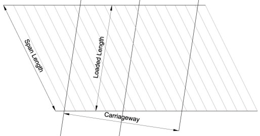
This is only true if there is load transfer between the longitudinal deck members. If there is poor transverse distribution or if deck beams are particularly skewed to the carriageway then the deck should be loaded with vehicles from Appendices D & E instead of HA loading (see clause 5.2)
The diagram above illustrates the loaded length for a single span deck, but the magnitude of the skew angle would warrant checking the HA analysis using Annex D & E vehicles. If in doubt then the Annex D & E vehicles should be used.
Back to Workshop | Back to Index
Clause 5.20
Problem:
What is the live load rating of a reinforced concrete bridge deck ?
Example:
Carriageway = 6m wide
Deck span = 12m (centre to centre of bearings for a simply supported single span)
Depth of concrete deck = 800mm
Depth of road construction = 250mm
Main longitudinal steel reinforcement = 32mm dia mild steel bars at 125mm centres.
Cover to reinforcement = 35mm
Assess for a metre width of deck :
BD 21/01
Cl. 5.6
Table 5.1
Number of notional lanes = 2
Notional lane width (bL) = 6.0 / 2 = 3.0m
Cl. 5.18.
From Table 5.2 with 12m loaded length :
W = 63.6 kN/m (per notional lane)
Knife Edge Load = 120 kN (per notional lane)
Cl. 5.23.
AF = 3.65 / 2.5 = 1.46
Cl. 5.26.
For a metre width of deck :
Adjusted HA UDL : W = 63.6 / (1.46 × 2.5) = 17.42 kN/m
KEL = 120 / (1.46 × 2.5) = 32.88 kN
Live Load Moment:
Cl. 3.7.
Table 3.1
γfL = 1.50 (Ultimate limit state)
Assessment HA loading for a metre width of deck :
W = 1.5 × 17.42 = 26.13 kN/m
KEL = 1.5 × 32.88 = 49.32 kN
Cl. 3.10.
γf3 = 1.1
Maximum mid span Bending Moment with KEL at mid span = Mult
Mult = 1.1 [ (26.13 × 122)/8 + (49.32 × 12)/4 ]
Live Load Mult = 1.1 (470 + 148) = 680 kNm
Note: Use of γf3
BD 56 & BD 61 - γf3 is used with the design strength so
Mult would be (470 + 148) = 618 kNm.
BD 44 - γf3 is used with the load effect so
Mult = 1.1 × 618 = 680 kNm.
Dead Load Moment:
Cl. 4.1.
Table 4.1.
For a metre width of deck :
Concrete UDL : w = 0.8 × 2400 × 9.81 / 1000 = 18.84 kN/m
Depth of Road construction = 250mm
From Note to Table 3.1: surfacing = 100mm
Surfacing UDL : w = 0.1 × 2300(Asphalt) × 9.81 / 1000 = 2.26 kN/m
Therefore fill depth = 250 - 100 = 150mm
Fill UDL : w = 0.15 × 2200(Miscellaneous) × 9.81 / 1000 = 3.24 kN/m
Cl. 3.7.
Table 3.1
Concrete γfL = 1.15
Surfacing γfL = 1.75
Fill γfL = 1.20
Assessment Dead Load w = (1.15 × 18.84) + (1.75 × 2.26) + (1.2 × 3.24)
Assessment Dead Load w = 29.51 kN/m
Cl. 3.10.
γf3 = 1.1
Maximum Dead Load mid span Bending Moment = Mult
Mult = 1.1 (29.51 × 122)/8)
Dead Load Mult = 1.1 (531) = 584 kNm
Total Mid Span Bending Moment = (Dead + Live) Moment
Total Mid Span Bending Moment = (584 + 680) = 1264 kNm
BD 44/15
Capacity of Reinforced Concrete Slab:
Cl. 5.4.2.
(Cl. 5.3.2)
Effective depth d = 800 - 35 - 32/2 = 749mm
fy = 230 N/mm2 (see BD 21/97 cl. 4.4)
fcu = 15 N/mm2 (see BD 21/97 cl. 4.7)
From Table 4A :
γms = 1.15,
γmc = 1.50
As = 6434 mm2/m (32mm bars at 125mm c/c)
z = [1-(0.84 × fy × As ×
γmc
) / (
fcu × b × d ×
γms
)] × d
z = [1-(0.84 × 230 × 6434 × 1.5) / (15 × 1000 × 749 × 1.15)] × d
z = 0.856 d (less than 0.95d)
Mu = (fy / γms) × As × z
Mu = (230 / 1.15) × 6434 × 0.856 × 749 × 10-6 = 825 kNm/m
BD 21/01
Live Load Rating:
Cl. 5.20.
Bending Capacity of Concrete Slab = 825 kNm (per metre width)
Assessment Load Mid Span Moment = 1264 kNm (584 dead + 680 live)
Live Load Capacity of Concrete Slab = 825 - 584 = 241 kNm
Hence Max Allowable K = 241 / 680 = 0.35
Cl. 5.22.
Fig 5/2
Assuming worst condition using Hp category
Loaded length = 12m hence:
Allowable Reduced Vehicle Load = 3 tonnes
(Group 2 Fire Engines will be allowed)
Note : The shear effects have to be checked in a similar manner to determine whether shear is more critical than bending.
Back to Workshop | Back to Index
Clause 6.17
Problem:
Can MEXE be used when the depth of the fill at the crown is greater than the thickness of the arch barrel?
Solution:
Many Authorities accept the MEXE analysis if the depth of fill(h) is made equal to the arch barrel thickness(d), i.e. h+d=2d
Back to Workshop | Back to Index
Clause 6.29
Problem:
When is a pier considered to be short and stocky?
Solution:
A number of Authorities have adopted a height to width ratio of 2:1 for the upper limit of a stocky pier; the height of the pier being measured between the top of foundations and the arch springing level.

David Childs
B.Sc, C.Eng, MICE
Last Updated: 28/01/2020