
Tutorial for Temperature Effects in Bridge Decks
There are two types of temperature loading effects to consider:
- Changes in effective bridge temperatures causing expansion and contraction in the deck.
- Differences in temperature between the top surface of the deck and at different levels throughout the depth of the deck causing the deck to distort.
1. Expansion and Contraction (Uniform Temperature)
Maximum and minimum shade air temperatures
have been recorded at weather stations over many years. These records are used to predict the maximum and minimum design temperatures that the bridge deck may experience
during its design life
. These temperatures are presented in the codes in the form of isotherm maps.
The maximum and minimum shade air temperatures are converted into 'effective' bridge temperatures Te,max and Te,min and multiplied by the coefficient of thermal expansion and the deck length to calculate how much the bridge deck will expand and contract. The expansion and contraction in the deck can either be accommodated by providing joints
and sliding bearings, or by restraining the movement and designing the structure to resist the forces developed.
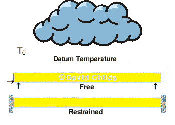
A datum temperature T0 is used to represent the effective bridge temperature at specific stages of construction. The deck will expand from T0 to Te,max and contract from T0 to Te,min.
T0 is used to either,
- in the case of a free moving deck, calibrate the gap for the expansion joint and to set the sliding bearing positions when these units are installed,
or
- in the case of a restrained deck, determine the magnitude of movement that the supporting structure has to accommodate after it has been made integral with the deck.
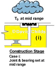
For free moving decks the value of T0 can be estimated at design stage, to establish the range of movement in the deck, and readjusted during construction for the actual temperature when the joints and bearings are installed.
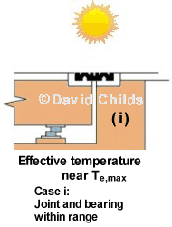
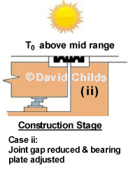
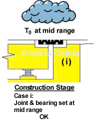
There are three possibilities for the effective bridge temperatures that could occur on site when the joints and bearings are installed:
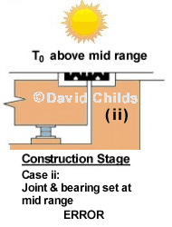
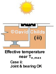
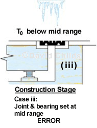
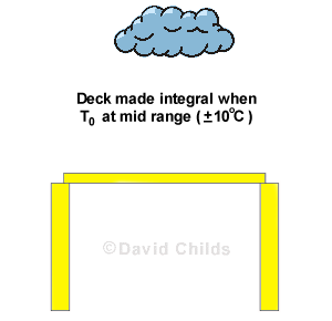
- When the effective bridge temperature T0 is at mid range then the joint and bearing can be set at mid movement range.
- When the effective bridge temperature T0 is above the mid range value then the joint gap needs to be reduced and the top bearing plate needs to be set forward towards the joint.
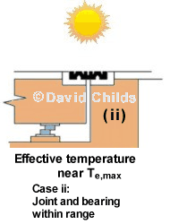
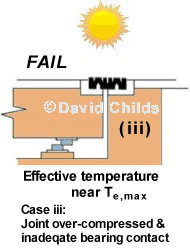
- When the effective bridge temperature T0 is below the mid range value then the joint gap needs to be increased and the top bearing plate needs to be set back away from the joint.
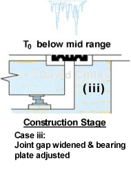
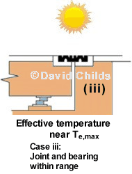
The joints and bearings will not be installed at the same time so there will be a different value T0 when each unit is installed. The diagram below demonstates how the joint and bearing needs to be set for the three T0 conditions, described above, to allow the units to function correctly.
If no adjustment is made to the joint or bearing, as shown below, for the effective bridge deck temperature that exists when the units are installed then permanent damage may result when extreme temperatures occur.
Correct

Fail
Fail
A horizontal force will be generated at the sliding bearing to overcome the static friction between the bearing plates when the deck expands and contracts. This horizontal force is transmitted to the fixed bearing on the fixed abutment (See Abutment Tutorial).
For durability reasons it is preferable not to provide expansion joints and bearings and to design the deck as acting integral with the supporting structure. This construction will restrain the deck expansion and contraction movement. BD 57/01 clause 2.3 says that, in principle, bridges with deck lengths not exceeding 60m and skews not exceeding 30° shall be designed as integral bridges.
The problem that arises when designing a restrained structure is deciding what the temperature (T0) will be when the deck is made integral with the supporting structure.
BA 42/96 clauses 2.10 and 2.11 get round the problem by specifying a ± thermal strain to cover the maximum expansion and contraction from the mid range temperature, but then applies a proviso that the bridge spans and abutments are joined
during construction at a temperature within ± 10°C of the mean between extreme minimum and extreme maximum shade air temperatures.
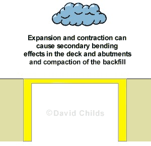
Once the deck has been made integral with the abutments then expansion and contraction of the deck will apply loads to the abutments. When the abutments move under these loads secondary bending effects can be produced in the deck and abutments.
The cyclic expansion and contraction movement of the deck can have a compaction effect on the backfill to the abutment walls. This effect is known as strain ratcheting and can result in a high earth pressures on the back of the wall. A modified earth pressure coefficient K* is used to model this condition.
In conjuction with the uniform temperature there is a non-linear temperature gradient through the deck, that is, the temperature varies at different levels throughout the depth of the deck.
The profile of the temperature gradient varies for different types of deck construction; there are four different deck types presented in the codes:
- Steel deck on steel girders
- Steel deck on steel truss or plate girders
- Concrete deck on steel box, truss or plate girders
- Concrete slab or concrete deck on concrete beams or box girders
Each deck type has two temperature profiles:
- To calculate the effects when the top surface of the deck is hotter than the core of the deck (known as ‘positive temperature difference’ or ‘heating temperature difference’)
- To calculate the effects when the top surface of the deck is cooler than the core of the deck (known as ‘reverse temperature difference’ or ‘cooling temperature difference’)
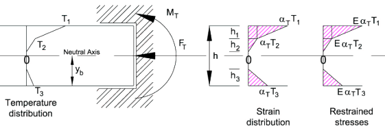
The solution for calculating the stress distribution through the deck under temperature difference conditions is to start from the assumption that the deck is rigidly restrained and then calculate the effects of removing the theoretical restraints.
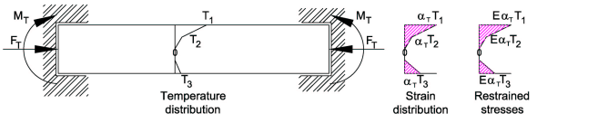
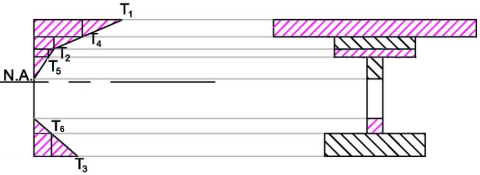
Let T1, T2 and T3 be the non-linear temperature distribution from the core temperature as shown below. Values for these temperatures are obtained from tables in the codes.
Let  T be the coefficient of thermal expansion (usually taken as 12x10-6/°C).
Let E be Young's Modulus for the deck material.
Then the strain at each depth where the temperature changes, and consequently the stress, can be calculated as shown below.
Let A be the cross-sectional area of the deck member, then when the axial restraint FT is removed a stress of
FT / A is released from the restrained stresses. The remaining restrained (locked in) stresses are shown in the diagram below.
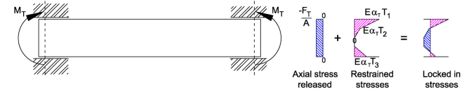
Let Z be the section modulus (I/y) of the deck member, then when the moment restraint MT is removed the deck flexes and a stress of MT / Z is released from the restrained stresses. The remaining restrained (locked in) stresses are shown in the diagram below.
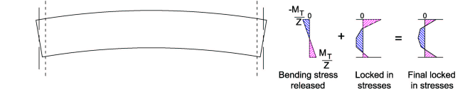
These final locked in stresses are often referred to as self-equilibrating stresses and need to be added to the stresses resulting from permanent and traffic loading when combinations including temperature effects are considered.
The self-equilibrating stresses have been determined by assuming that the restraining force FT and moment MT can be fully released. This can be achieved if the deck is provided with joints and bearings which allow the ends of the deck to rotate and translate, and if the deck is not continuous (deck is simply supported single span).
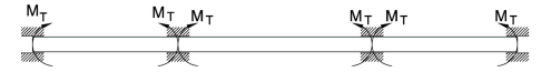
If the deck is multi-span and continuous then there will be a redistribution of the releases.
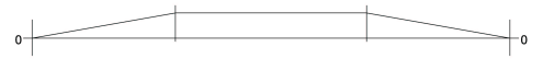
The same procedure as before applies. The axial force FT can be released fully by allowing the deck to expand and contract with the provision of suitable bearings and end joints.The restrained moment diagram then is as shown below:
Three span continuous deck with axial restraint removed.
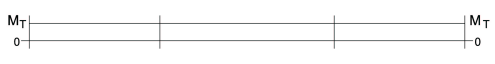
Moment Diagram.
The restraining moments MT at the internal supports balance each other so these restraints can be removed and the deck can be restrained by applying MT at the ends of the deck only. These end restraints are released by applying an equal and opposite moment to the deck as shown below:
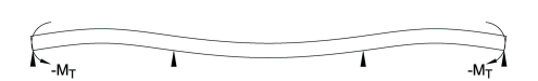
-MT applied at the ends of the deck to balance end restraints.
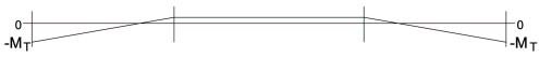
Moment Diagram
The effects of removing the moment restraint can then be achieved by superimposing the two moment diagrams as shown below.
Alternatively you can download a line beam spreadsheet which will distribute MT for a multi-span continuous deck.
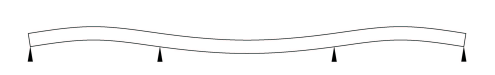
Deflected profile of deck after removing restraints.
Final Moment Diagram
The stresses in the deck from the final moment diagram shown above need to added to the self-equilibrating stresses to achieve the total stress arising from the temperature difference loading.
How to calculate FT and MT
The restrained stress diagram is divided into sufficient sections, of depth h1 etc., to determine the stress where there is a change in beam width, a change in the beam material or change in temperature. The example shown in the diagrams is for a solid slab deck and will have the same width and material over its full depth so we only need to provide sections at changes in temperature.
Let the width of each section be B.
Let h1, h2 etc, be the depth of each section.
Then the Restraining force FT is the average restained stress multiplied by the area of the section:
FT =  σBzdz
σBzdz
FT = ETB{[h1(T1+T2)/2]+[h2T2/2]+[h3T3/2]}
The Restraining Moment MT is found by summing the force on each section multiplied by the distance of its centroid to the neutral axis.
It is convenient to divide the restrained stress diagram into rectangles and triangles as the position of the centroid of these shapes is known.
Let z be the distance from the neutal axis to the centroid of the force on each section then:
MT = σzBzdz
For a solid rectangular deck the depth to the neutral axis yb = yt = h/2
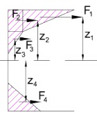
F1 = ETB(T1-T2)h1/2
F2 = ETBT2h1
F3 = ETBT2h2/2
F4 = ETBT3h3/2
z1 = h/2 - h1/3
z2 = h/2 - h1/2
z3 = h/2 - h1 - h2/3
z4 = -(h/2 - h3/3)
MT = F1z1+F2z2+F3z3+F4z4
When the cross section varies then the temperature at the change of section needs to be interpolated (as T4, T5 and T6 shown below).
Alternatively you can purchase the differential temperature spreadsheet (105.zip to BS 5400, or 106.zip to Euro Codes) which will calculate the self-equilibrating stresses and releasing moment and force for any of the four bridge deck types listed in the codes.
Contact David Childs

David Childs
B.Sc, C.Eng, MICE
Last Updated: 28/01/2020