
Buried Box Design Example to BD 31
The following example is not a definitive solution for the design of a box culvert, but provides one solution to demonstrate the principles involved when considering design standards BD 31 and BS 5400. The example is presented to promote comment and discussion.
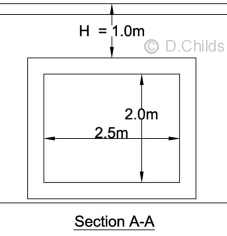
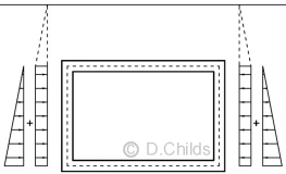
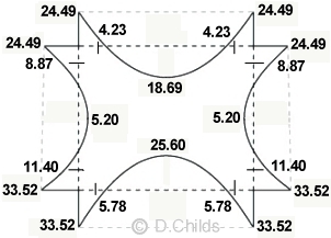
Design the in-situ concrete culvert shown below to carry HA and 45 units of HB loading. Analyse the culvert using a unit strip method. The bridge site is located south east of Oxford (to establish the range of shade air temperatures).
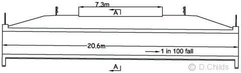
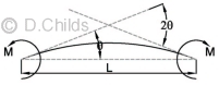
Long-section through culvert
The ground investigation report shows the founding strata to be a cohesionless soil having an angle of shearing resistance (φ) = 32° and a safe bearing capacity of 300kN/m2 and classified as 'not hard' material.
Maximum height of ground water is 1m above the invert level of the culvert.
Maximum height of water inside the culvert is 1.8m above the invert level of the culvert.
Backfill material will be Class 6N with a density (γ) = 19kN/m3.
Fill over the culvert consists of 0.5m of Class 6N overlaid with 0.3m of road sub-base with a density (γ) = 20kN/m3 and 0.2m of carriageway construction with a density (γ) = 24kN/m3
Loading
Consider loading on 1m strip of the culvert.
- Self Weight
Assume a wall thickness of 300mm and concrete density (γ) = 25kN/m3
Nominal total load = 25 × [(3.1 × 2.6) - (2.5 × 2.0)] = 76.5kN
γfL,SLS = 1.0, γfL,ULS = 1.2
Design Load for Diagrams 1, 3 & 4 = 1.1 × 1.2 × 76.5 = 101kN
Design Load for Diagrams 2, 5, 6 & 7 = 1.0 × 1.0 × 76.5 = 76.5kN - Fill Over Box
Nominal load per metre = 19 × 0.5 + 20 × 0.3 = 15.5kN/m
γfL,SLS = 1.0, γfL,ULS = 1.2 - Surfacing
The top 200mm is considered as surfacing
Nominal load per metre = 24 × 0.2 = 4.8kN/m
γfL,SLS = 1.2, γfL,ULS = 1.75
SDL (Superimposed Dead Load)
β for 'not hard' foundation material = 1.15 (from Figure 3.1)
Design Load for Diagrams 1, 3 & 4 = 1.1 × 1.15 (1.2 × 15.5 + 1.75 × 4.8) = 34.2kN/m
Design Load for Diagrams 2, 5 & 6 = 1.0 × 1.0 × (15.5 + 4.8) = 20.3kN/m
Design Load for Diagram 7 = 1.15 × (15.5 + 4.8) = 23.3kN/m - Settlement
The MCHW Specification Series 600 ensures that any soft spots are removed from the foundation and replaced with suitable material. This will ensure that any differential settlement for a relatively short span box will be negligible. Also a suitable factor of safety will be applied to the allowable bearing pressure when checking the maximum bearing pressure under the box to ensure that settlement will be minimal.
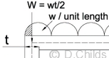
- HA 100kN wheel load
Contact patch area to produce 1.1N/mm2 = √(100000/1.1) = 302 × 302mm
Dispersed area on top of box = 302 + 2 × 1000 / 2 = 1302 × 1302mm
Dispersed area to neutral axis of box = 1302 + 2 × 300 / 2 = 1602 × 1602mm
Edge of carriageway to headwall at end of structure > (1000 / 2 + 300 / 2) = 650mm hence full dispersal can be considered
Wheel load on dispersed area = 100 / 1.6022 = 39kN/m2
Combination 1: γfL,SLS = 1.2, γfL,ULS = 1.5
Combination 3: γfL,SLS = 1.0, γfL,ULS = 1.25 - HA UDL & KEL load not considered (Clause 3.2.1 (a)(ii) H > 0.6m)
- 45 units of HB load
Wheel load = 45 × 10 / 4 = 112.5kN
Contact patch area to produce 1.1N/mm2 = √(112500/1.1) = 320 × 320mm
There are no longitudinal joints in the structure therefore the code allows a transverse distribution down to the neutral axis of the roof slab (estimated as half the depth of the slab).
Depth from carriageway level to neutral axis of roof slab = 1000 + 300 / 2 = 1150mm
4 wheels on each axle are spaced at 1m so, at 1:2 gradient, the transverse dispersal lines will overlap at a depth = 1000 - 320 = 680mm < 1150mm hence overlap and need to consider 4 wheels.
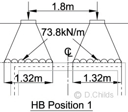
Transverse dispersal of axle load = 3000 + 320 + (2 * 1000 / 2) + (2 * 300 / 2) = 4620mm
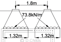
Front and rear pair of axles are spaced at 1.8m so, at 1:2 gradient, the longitudinal dispersal lines will overlap at a depth = 1800 - 320 = 1480mm > 1150mm hence no overlap and need to consider each axle separately.
Longitudinal dispersal of 1 axle load = 320 + (2 * 1000 / 2) = 1320mm
Edge of carriageway to headwall at end of structure > 1000 / 2 + 300 / 2 = 650mm hence full dispersal can be considered in the transverse direction.
Axle load on dispersed area = 4 × 112.5 / (4.62 × 1.32) = 73.8kN/m2
Combination 1: γfL,SLS = 1.1, γfL,ULS = 1.3
Combination 3: γfL,SLS = 1.0, γfL,ULS = 1.1
ULS Pressure from HA wheel load = 1.1 × 1.5 × 39kN/m2 = 64.4kN/m2
ULS Pressure from HB axle load = 1.1 × 1.3 × 73.8kN/m2 = 105.5kN/m2
64.4kN/m « 105.5kN/m2 ∴ HB loading will be critical. - Temperature Load
From Table 3.1:
Span to width ratio = Xclear / LT = 2.5 / 20.6 = 0.12 (< 0.2)
For Temperature Range Calculation: 0.75 < H ≤ 1.0 ∴ Tmin = 4° Tmax = 16°
The box structure will be modelled assuming the members flex about their centre-line so the span of the roof slab is assumed to be 2.5 + 0.3 = 2.8m
Clause 3.2.8 (b)(i): Roof slab expansion = (16° - 10°) × 12 × 10-6 × 2.8 × 1000 = 0.2mm
Roof slab contraction = (10° - 4°) × 12 × 10-6 × 2.8 × 1000 = 0.2mm
Combination 3: γfL,SLS = 1.0, γfL,ULS = N/A
For Differential Temperature Calculation: Positive and Reverse temperature gradients are obtained from BD 37/01 Figure 9, Group 4 type structure
Combination 3: γfL,SLS = 0.8, γfL,ULS = 1.0 Reduction Factor η = 0.33 - Traction Load
H > 0.6m ∴ HA traction not required.
Clause 3.2.7: Consider 45 units of HB to BD 37 Clause 6.10.2:
Nominal Load for HB = 25% of 45units × 10kN × 4axles = 450kN
Distribute load between eight wheels of two axles = 450 / 2 = 225kN per axle
Clause 3.2.7(e): Reduction Factor Kt = (LL - H) / (LL - 0.6) = (2.5 + 0.6 - 1.0) / (2.5 + 0.6 - 0.6) = 0.84
Clause 3.2.7(g): Centre of traction force to edge of kerb = (3.0 + 0.32) / 2 = 1.66m
Distance from kerb to nearest edge of structure = (20.6 - 7.3) / 2 = 6.65m
Hence Et = 1.66 + 6.65 = 8.31m. So 2Et = 16.62m (> 3 + C = 3.32)
Traction load per metre width of box = 0.84 × 225 / 16.62 = 11.7kN per axle
When two axles are on the structure the traction load per metre width of box = 2 × 11.7kN = 23.4kN
Combination 4: γfL,SLS = 1.0, γfL,ULS = 1.1 - Skidding Load & Centrifugal Load
H > 0.6m so these loads do not need to be considered.
Analysis
A moment distribution analysis is a suitable method of distributing loads throughout the box structure. Loads can be applied to the model to determine the fixed end moments on each member.
The relative stiffness of the members can be determined from EI/L. E is the short-term (for live loads) or long-term (for permanent loads) modulus of elasticity. As E and I will be the same for each member the relative stiffness can be calculated from 1/L.
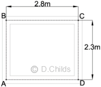
Members AB and CD: 1/L = 1 / 2.3 = 0.435
Members BC and DA: 1/L = 1 / 2.8 = 0.357
Distribution Factors:
AB at A, AB at B, CD at C, CD at D = 0.435 / (0.435 + 0.357) = 0.549
AD at A, AD at D, BC at B, BC at C = 0.357 / (0.435 + 0.357) = 0.451
Fixed End Moments
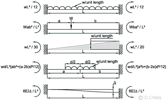
Standard solutions to Fixed End Moments
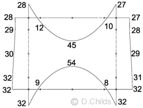
Load Case Diagram A/1a
Diagram A/1a
Apply loading as shown in Diagram A/1a in Appendix A where :
Earth Pressure Coefficient K = 0.6 for both live load surcharge and backfill earth pressures.
The factors shown in the table under Diagram A/1a in BD 31 are for ULS condition.
The maximum load effects in the members will be obtained with no water inside the culvert.
Dead Load
LD1) UDL on roof slab:
Surfacing = γf3γfLβ × 4.8 = 1.1 × 1.75 × 1.15 × 4.8 = 10.63kN/m
Fill = γf3γfLβ × 15.5 = 1.1 × 1.2 × 1.15 × 15.5 = 23.53kN/m
Self weight of roof = γf3γfL × 25 × 0.3 = 1.1 × 1.2 × 7.5 = 9.9kN/m
Total UDL on roof member = 10.63 + 23.53 + 9.9 = 44.06 kN/m
Fixed End Moments for UDL (at B and C for member BC) = wL2/12 = 44.06 × 2.82 / 12 = 28.79 kNm
Simply supported mid-span moment = wL2/8 = 44.06 × 2.82 / 8 = 43.18 kNm
LD2) UDL on floor slab:
UDL above roof = 10.63 + 23.53 = 34.16kN/m
Self weight of box = γf3γfL × 76.5 / 2.8 = 1.1 × 1.2 × 76.5 / 2.8 = 36.06kN/m
Pressure on foundation ↑ = 34.16 + 36.06 = 70.22 kN/m
Self weight of floor member (same as roof) ↓ = 9.9 kN/m
Net UDL on floor member = 70.22 - 9.9 = 60.32 kN/m
Fixed End Moments for UDL (at A and D for member AD) = wL2/12 = 60.32 × 2.82 / 12 = 39.41 kNm
Simply supported mid-span moment = wL2/8 = 60.32 × 2.82 / 8 = 59.11 kNm
LD3) Backfill pressures on walls:
- Increase in horizontal pressure due to backfill between centre-line of roof and floor (triangular distribution) = K × 2.3 × 19 = 0.6 × 2.3 × 19 = 26.2kN/m
Design pressure = γf3γfL × 26.2 = 1.1 × 1.5 × 26.2 = 43.23kN/m
Fixed End Moments for triangular loading = wL2/20 (at A and D for members AB and CD respectively) = 43.23 × 2.32 / 20 = 11.43kNm
Fixed End Moments for triangular loading = wL2/30 (at B and C for members AB and CD respectively) = 43.23 × 2.32 / 30 = 7.62kNm
Simply supported mid-span moment = 0.75wL2/12 = 0.75 × 43.23 × 2.32 / 12 = 14.29 kNm - Surcharge from fill & surfacing above centre-line of roof = γf3γfL × 4.8 + γf3γfL × (15.5 + 0.15 × 19) = 1.1(1.75 × 4.8 + 1.2 × 18.35) = 33.46kN/m
From table below Diagram A/1a: K = 0.6 γfL = 1.5 (γf3 has already been applied)†
Hence uniform horizontal surcharge pressure on walls = 0.6 × 1.5 × 33.46 = 30.1kN/m
Fixed End Moments for UDL (at A and B for member AB, and at C and D for member CD) = wL2/12 = 30.1 × 2.32 / 12 = 13.27 kNm
Simply supported mid-span moment = wL2/8 = 30.1 × 2.32 / 8 = 19.9 kNm
Total simply supported mid-span moment due to backfill = 14.29 + 19.9 = 34.19 kNm.
Note †: γf3 is shown in the Diagrams to be applied to both the fill and surfacing over the box (SDL), and also to the horizontal earth pressures. BS 5400 Part 1: Clause 3.3.2 says γf3 takes account of inaccurate assessment of the effects of loading, unforseen stress distribution in the structure, and variations in dimensional accuracy achieved in construction. It is believed that the factor should only be applied once when assessing the effects of the SDL surcharge effects on the side of the structure.
Distribute Dead Load Fixed End Moments
Notation: Clockwise moments assumed positive.
A
B
C
D
A
Distr.Fctr's
0.549
0.549
0.451
0.451
0.549
0.549
0.451
0.451
LD1
-28.79
28.79
LD2
-39.41
39.41
LD3i
-11.43
7.62
-7.62
11.43
LD3ii
-13.27
13.27
-13.27
13.27
Total FEM's
-24.70
20.89
-28.79
28.79
-20.89
24.70
-39.41
39.41
Release
-8.08 ↘
↙ 4.34
3.56 ↘
↙ -3.56
-4.34 ↘
↙ 8.08
6.63 ↘
↙-6.63
Carry-over
2.17
-4.04
-1.78
1.78
4.04
-2.17
-3.31
3.31
Release
-3.01 ↘
↙ 3.20
2.62 ↘
↙ -2.62
-3.20 ↘
↙ 3.01
2.47 ↘
↙ -2.47
Carry-over
1.60
-1.50
-1.31
1.31
1.50
-1.60
-1.23
1.23
Release
-1.55 ↘
↙ 1.54
1.27 ↘
↙ -1.27
-1.54 ↘
↙ 1.55
1.28 ↘
↙ -1.28
Carry-over
0.77
-0.77
-0.63
0.63
0.77
-0.77
-0.64
0.64
Release
-0.77
0.77
0.63
-0.63
-0.77
0.77
0.64
-0.64
Sum
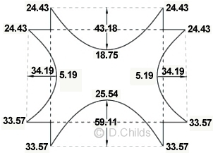
-33.57
24.43
-24.43
24.43
-24.43
33.57
-33.57
33.57
ULS Dead Load Bending Moment Diagram
Moment Distribution Results
Notation: Values are shown on the tension face of the member.
Note: load factors for dead loads are the same for all combinations (1, 3 and 4).
Moment distribution is reasonably straight forward when the loading is symmetrical. When unsymmetrical loading is applied (as for moving traffic loads or braking and acceleration forces) then there is the potential for the roof slab to move horizontally, relative to the floor slab, and an additional moment distribution analysis has to be carried out to determine the effects of “sway”. A more efficient method of analysis would be to use a plane frame model. A simple spreadsheet is available from this website.
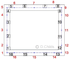
Plane Frame Model
Nodes have been located at corners, mid-span and at points 'd' away from the inside face of the culvert, where d = effective depth to centre of reinforcement measured from the compression face. d is estimated as 300 - 70 = 230mm.
Length of Members 1, 4, 5, 8, 9, 12, 13, 16 = 300 / 2 + 230 = 380mm.
Length of Members 6, 7, 14, 15 = 2800 / 2 -380 = 1020mm.
Length of Members 2, 3, 10, 11 = 2300 / 2 -380 = 770mm.
Plane Frame Results
The results of the plane frame analysis give similar values for the moments that were obtained from the moment distribution method.
A minor adjustment can be made to improve the accuracy by including point loads to represent the load beyond the centre-line of the walls. The diagram shows load on the roof, but can also be applied to the floor slab. This modification has not been included in the results.
Live Load
LD4) Temperature Effects:
- Expansion in roof slab. This effect is only considered in Combination 3 at SLS, but is included here for completeness.
Expansion = γf3γfL × 0.2 = 1.0 × 1.0 × 0.2 = 0.2mm
Using short-term value of E for live load condition and assume an initial concrete strength for fcu of 40N/mm2: E = 31kN/mm2 (from Table 3 of BS 5400 Pt.4)
I = 1000 × 3003/12 = 2.25 × 109mm4
Fixed End Moments for UDL (at A and B for member AB, and at C and D for member CD) = 6EIΔ/L2 = 6 × 31 × 2.25 × 109 × 0.2 × 10-9 /2.32 = 15.82kNm
Contraction in roof slab is of the same magnitude as Expansion so fixed end moments will be of the same magnitude but applied in the opposite direction.
- Differential Temperature in roof slab
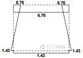
Table 3.1 says to use BD 37 Fig. 9 Group 4 with a reduction factor η = 0.33- Positive Temperature
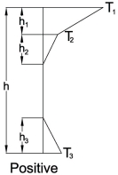
h = 300mm
h1 = 0.3 × h = 90mm
h2 = 100mm
h3 = 0.3 × h = 90mm
T1 = 10.25°C
T2 = 3.25°C
T3 = 1.0°C
Following the procedure described in the Temperature Effects Tutorial we get:
F1 = E TB(T1-T2)h1/2
F2 = E
TBT2h1F3 = E
TBT2h2/2F4 = E
TBT3h3/2
z1 = h/2 - h1/3z2 = h/2 - h1/2
z3 = h/2 - h1 - h2/3
z4 = -(h/2 - h3/3)
MT = F1z1+F2z2+F3z3+F4z4
E
TB = 31 × 12×10-6 × 1000 = 0.372
F1 = 0.372×(10.25 - 3.25)×90/2 = 117.18kN
F2 = 0.372×3.25×90 = 108.81kN
F3 = 0.372×3.25×100/2 = 60.45kN
F4 = 0.372×1.0×90/2 = 16.74kN
z1 = 0.15 - 0.09/3 = 0.12m
z2 = 0.15 - 0.09/2 = 0.105m
z3 = 0.15 - 0.09 - 0.1/3 = 0.027m
z4 = -(0.15 - 0.09/3) = -0.12m
Releasing Force FT = F1 + F2 + F3 + F4 = 117.18 + 108.81 + 60.45 + 16.74 = 303.2kN (Tension)
Design Releasing Force FT = γf3γfLη × 303.2 = 1.1 × 1.0 × 0.33 × 303.2 = 110.06kN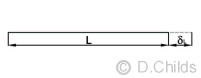
Axial ReleaseExtension in roof member due to release force = δL = FTL / AE
δL = 110.06 × 2.8 / (0.3 × 31×106) = 33.1×10⁻⁶m
The design axial displacement is applied to the structure in the opposite direction to release force i.e. contraction = 33.1×10⁻⁶m .
Although this displacement is negligible it will be added into the calculation for completeness.
Releasing Moment MT = 117.18×0.12+108.81×0.105+60.45×0.027-16.74×0.12 = 25.1kNm (hogging)
Design Releasing Moment MT = γf3γfLη × 25.1 = 1.1 × 1.0 × 0.33 × 25.1 = 9.11kNm (hogging)
Moment ReleaseAngular rotation roof member due to release moment = 2θ = MTL / EI
2θ = 9.11 × 2.8 / (31×106 × 0.00225) = 0.000366 radians.
Hence rotation applied a each end = θ = 0.000366 / 2 = 0.000183 radians.
The design rotation is applied in the opposite direction to release moment.
- Reverse Temperature
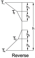
h = 300mm
h1 = h4 = 0.2 × h = 60mm
h2 = h3 = 0.25 × h = 75mm
T1 = 3.25°C
T2 = 0.95°C
T3 = 0.75°C
T4 = 2.5°CRepeating the procedure gives release FT = 106.86kN (Compression) and MT = 1.515kNm (Sagging)
Design release force to roof member (ULS) = γf3γfLηFT = 1.1 × 1.0 × 0.33 × 106.86 = 38.8kN (Compression)
Extension in roof member = δL = FTL / AE
δL applied to structure = 38.8 × 2.8 / (0.3 × 31×106) = 11.7×10⁻⁶m (Extension)
Design release moment to roof member (ULS) = γf3γfLηMT = 1.1 × 1.0 × 0.33 × 1.515 = 0.55kNm (sagging)
Angular rotation roof member = 2θ = MTL / EI
2θ = 0.55 × 2.8 / (31×106 × 0.00225) = 0.000022 radians.
Hence rotation applied a each end of structure = θ = 0.000022 / 2 = 0.000011 radians (hogging).
A simple spreadsheet is available from this website for determining the Differential Temperature effects. The results of the Differential Temperature spreadsheet analysis give similar values for the release forces and moments that were obtained above.
The free plane frame spreadsheet available from this website will analyse the displacements and rotations to produce the distribution effects in the structure.
The results of the Positive Temperature Difference and the Reverse Temperature Difference effects on the structure are shown in the moment diagrams below.
Positive Temperature Release Moments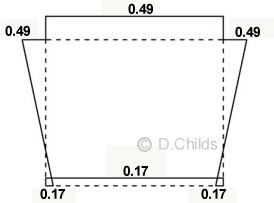
Reverse Temperature Release Moments
The self equilibrating stresses need not be applied to the insitu concrete box; they need only be considered for prestressed concrete roof slabs (see BD 31 Clause 3.2.8(b)(ii)).
- Positive Temperature
LD5) UDL HB surcharge pressure on walls:
45 units of HB surcharge = 20 kN/m2
From table below Diagram A/1a: K = 0.6
Hence horizontal surcharge pressure on walls = K × γf3γfL × 20 = 0.6 × 1.1 × 1.5 × 20 = 19.8kN/m
Fixed End Moments for UDL (at A and B for member AB, and at C and D for member CD) = wL2/12 = 19.8 × 2.32 / 12 = 8.73 kNm.
Note: Load factors are the same for all combinations (1, 3 and 4).
The results of a plane frame analysis produce the bending moment diagram shown.
HB Surcharge Moments
LD6) HB vehicle over roof Position 1:
The HB vehicle needs to be positioned to obtain the worst effect in each member. This will result in several calculations with the axles in different positions.
A spreadsheet (101a) is available for determining the load effects envelope for moving loads crossing a box structure.
Only one position will be considered in this example to demonstrate the principle. Position the edge of the udl at node 5 as shown.
Design UDL for Combination 1 = γf3γfLw = 1.1 × 1.3 × 73.8 = 105.5kN/m
Design UDL for Combination 3 = γf3γfLw = 1.1 × 1.1 × 73.8 = 89.3kN/m
The Plane Frame Results give values for reactions from the eccentric loading for Combination 1 which are:
Ry1 = 125.274kN Ry13 = 119.486kN
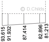
Replacing the reactions by a trapezoidal bearing pressure:
P/A = (125.274 + 119.486) / (1 × 2.8) = 87.414kN/m2
M/Z = {1.4 × (125.274 - 119.486)} / (1 × 2.82 / 6) = 6.201kN/m2
At Node 1 Bearing Pressure = 87.414 + 6.201 = 93.615kN/m2
At Node 13 Bearing Pressure = 87.414 - 6.201 = 81.213kN/m2
Re-running the plane frame analysis for HB vehicle Combination 1, position 1 with the trapezoidal bearing pressure we get the bending moment diagram shown below. Combination 3 moments can be obtained by factoring Combination 1 moments by 1.1/1.3 = 0.846
Live Load Bending Moment (kNm) Results Due to HB Vehicle Position 1
Combination 1
Combination 3
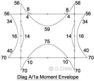
Results for Diagram A/1a can now be achieved by adding the moments for Dead Load, HB surcharge, HB vehicle on roof and temperature effects. As the HB vehicle can be positioned anywhere over the roof then a moment envelope can be produced for the maximum and minimum moments. The results show that Combination 1 loading is critical.
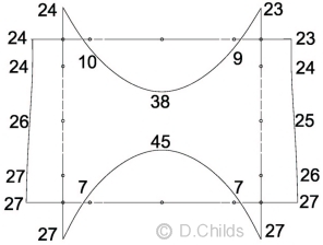
Load Case Diagram A/2a
Reduced load factors on dead loads give:
UDL on roof slab
Surfacing = 1.0 × 1.0 × 4.8 = 4.8kN/m
Fill = 1.0 × 1.0 × 15.5 = 15.5kN/m
Roof self weight = 1.0 × 1.0 × 7.5 = 7.5kN/m
Total UDL on roof member = 4.8 + 15.5 + 7.5 = 27.8 kN/m
Diagram A/2a
UDL on floor slab
UDL above roof = 4.8 + 15.5 = 20.3kN/m
Self weight of box = 1.0 × 1.0 × 76.5 / 2.8 = 27.32 kN/m
Pressure on foundation ↑ = 20.3 + 27.3= 47.6 kN/m
Self weight of floor member (same as roof) ↓ = 7.5 kN/m
Net UDL on floor member = 47.6 - 7.5 = 40.1 kN/m
Backfill pressures on walls: triangular distribution as for diagram A/1a = 43.23kN/m (at base centre-line).
SDL surcharge pressure = 0.6 × 1.5 × 1.1 × (4.8 + 15.5 + 0.15 × 19) = 22.92kN/m
UDL HB surcharge pressure on walls as for diagram A/1a
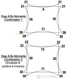
Results for Diagram A/2a can now be achieved by adding the moments for Dead Load, HB surcharge and temperature effects.
There are no envelope diagrams as the live load is static.
It can be seen that Combination 3 loading is critical. This is because there is no reduction for the applied loads in Combination 3 shown in Table 3.2 of BD 31/01.
Load Case Diagram A/3a
Two load cases can be considered:
- with water pressures inside the culvert (for maximum tension on outside face of walls)
- without water pressures inside the culvert (for maximum tension on inside face of base slab)
Total UDL on roof member as for diagram A/1a = 44.06 kN/m
Net UDL on floor member for diagram A/1a = 60.32 kN/m ↑
Depth of water inside culvert = 1.8m
Apply partial factors to water density to allow for solids in suspension.
Pressure of water on base = 1.1 × 1.2 × 10 × 1.8 = 23.76kN/m
Assume that this pressure will be balanced by an equal pressure on the underside of the base.
Diagram A/3a
Backfill partial factors for diagram A/1a = K γf3γfL = 0.6 × 1.5 × 1.1 = 0.99
Backfill partial factors for diagram A/2a = K γf3γfL = 0.2 × 1.0 × 1.0 = 0.2
Hence backfill pressures on walls:
At base of wall triangular pressure = 43.23 × 0.2 / 0.99 = 8.73 kN/m
UDL from fill surcharge = 30.1 × 0.2 / 0.99 = 6.08 kN/m
Triangular pressure from water inside culvert = 23.76 kN/m at base.
(Apply horizontal water pressure between nodes 1 and 4 as an approximation of the loading)
HB live load as for diagram A/1a (no surcharge).
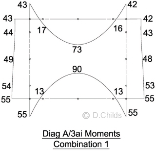
Results for Dead Load (with water inside culvert) are added to the HB position 1 results and compared for Combinations 1 and 3
The critical load combination is Combination 1.
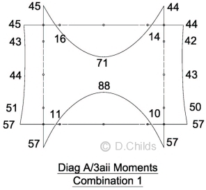
Results for Dead Load (without water inside culvert) are added to the HB position 1 results and compared for Combinations 1 and 3
The critical load combination is Combination 1.
Load Case Diagram A/4a
Traction load per metre width of box = 23.4kN
γfL=1.1
γf3=1.1
Design traction load = 1.1 × 1.1 × 23.4 = 28.3kN
Diagram A/4a
45 units of HB surcharge = 20 kN/m2
Active surcharge pressure = 20 × KγfLγf3 = 20 × 0.33 × 1.5 × 1.1 = 10.89kN/m2
Horizontal force from surcharge = 2.6 × 10.89 = 54.3kN
Increase in horizontal pressure due to backfill between top of roof and foundation level (triangular distribution) = K × 2.6 × 19 = 0.33 × 2.6 × 19 = 16.3kN/m
Design pressure = γf3γfL × 16.3 = 1.1 × 1.5 × 16.3 = 26.9kN/m
Horizontal force from backfill = 26.9 × 2.6 / 2 = 35kN
Surcharge from fill & surfacing above top of roof = γf3γfL × 4.8 + γf3γfL × 15.5 = 1.1(1.75 × 4.8 + 1.2 × 15.5) = 29.7kN/m
Hence design uniform horizontal surcharge pressure on walls = KγfL × 29.7 = 0.33 × 1.5 × 29.7 = 14.7kN/m
Horizontal force from fill surcharge = 14.7 × 2.6 = 38.2kN
Total active horizontal force = 28.3 + 54.3 + 35.0 + 38.2 = 155.8kN
At-rest pressures on passive side of box:
Horizontal force from backfill = Kγf3γfL × 19 × 2.62 / 2 = 0.6 × 1.0 × 1.0 × 19 × 2.62 / 2 = 38.5kN
SDL surcharge pressure = 29.7kN/m
Horizontal force from fill surcharge = 0.6 × 29.7 × 2.6 = 46.3kN
Total passive horizontal force = 38.5 + 46.3 = 84.8kN
Horizontal force to be resisted by friction on base = 155.8 - 84.8 = 71kN
Weight on base = W = 1.1(1.75 × 4.8 + 1.2 × 15.5 + 1.2 × 76.5) = 130.7kN
Friction force = Wtanφ = 130.7 × tan32° = 81.7kN > 71kN say OK
Note:
- The position of the supports for the structural model will have a significant effect on the distribution of loads throughout the structure. As the friction under the base will balance the horizontal loads then providing a horizontal restraint at node 1 will be satisfactory.
- Although sliding is checked with Diagram A/6a the model structure needs to remain in equilibrium. If the at-rest soil pressures (K = 0.6 on the right-hand side of the box) provide a greater horizontal force than is required to resist the active pressures (K = 0.33 on the left-hand side of the box) then the K value of 0.6 should be reduced to achieve a balance. This is acknowledged in Diagram A/6a and is also mentioned in PD 6694-1 for the Eurocodes.
Vertical loads for the model are as for Diagram A/1a.
Dead Load from fill:
Triangular distribution of earth pressure on active side: at centre-line of base = 0.33 / 0.6 × 43.23 = 23.78kN
Uniform horizontal surcharge pressure on active side = 0.33 / 0.6 × 30.1 = 16.56kN
Triangular distribution of earth pressure on passive side: at centre-line of base = 1.0 / (1.5 × 1.1) × 43.23 = 26.2kN
Uniform horizontal surcharge pressure on passive side = 1.0 / (1.5 × 1.1) × 30.1 = 18.24kN
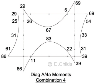
Results for Dead Load are added to the HB position 1 results together with HB surcharge and traction load on one side of the box to obtain Combination 4 Loads.
Temperature loads are not considered with traction loading so Combination 3 is not relevant.
Load Case Diagram A/5a
Vertical Dead loading as Diagram A/2a.
Horizontal earth pressures and traction loading as Diagram A/4a.
HB vertical live loading as loading as Diagram A/1a but divide by [1.1 × 1.3] for combination 1 and [1.1 × 1.1] for combination 3.
Diagram A/5a
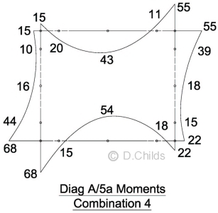
Results for Dead Load are added to the factored HB position 1 results together with HB surcharge and traction load on one side of the box to obtain Combination 4 Loads.
Temperature loads are not considered with traction loading so Combination 3 is not relevant.
Load Case Diagram A/6a
Diagram A/6a is used to check the stability of the structure.
HB traction load is distributed between eight wheels of two axles of the vehicle.
Position 1 of the HB vehicle shows that part of the distributed load is off the deck. Assume that full traction from two axles is applied but use the reduced vertical load from the wheels.
Diagram A/6a
Nominal HB vertical load (assume patch load at edge of box) = (1.32 + 1.3) × 73.8 = 193.3kN
Vertical load from surfacing and fill over the box = (4.8 + 15.5) × 3.1 = 62.9kN
Vertical load from culvert self weight = 76.5kN
For maximum uplift effect assume the culvert to be empty with ground water at 1m above soffit level as specified in the brief.
Uplift force = γwater × width × depth = 10 × 3.1 × 1.3 = 40.3kN
Design uplift force = γf3 × γfL × 40.3kN = 1.1 × 1.1 × 40.3 = 48.8kN
Net downward force = 193.3 + 62.9 + 76.5 - 48.8 = 283.9kN
Frictional resistance on base of culvert = Wtanφ = 283.9 × tan32° = 177.4kN
Horizontal traction loading from Diag A/4a = 28.3kN
Horizontal force from HB surcharge from Diag A/4a = 54.3kN
Horizontal force from backfill from Diag A/4a = 35kN
SDL surcharge 4.8 + 15.5 = 20.3kN/m
Horizontal force from SDL = 0.33 × 1.1 × 1.5 × 20.3 × 2.6 = 28.7kN
Total horizontal active force = 28.3 + 54.3 + 35 + 28.7 = 146.3kN
A reduction should be made for the submerged density of the fill below the ground water level, however 146.3kN < 177.4kN therefore friction alone will prevent sliding.
It is not clear whether the traction force will act on the structure when the vehicle is positioned off the roof slab; this would certainly be the most onerous position as specified in the code. Eurocode document PD 6694-1 Clause 10.2.8.2 is more specific saying 'braking or acceleration force applied to the top of the roof need not be taken as greater than the friction force that can be generated between the earth and the roof, taking the weight of the vehicle into account.'. This suggests that the vehicle must be over the roof of the structure to transmit the traction force.
If the worst case is assumed then net downward force without HB vertical load = 62.9 + 76.5 - 48.8 = 90.6kN
Frictional resistance on base of culvert = Wtanφ = 90.6 × tan32° = 56.6kN
Horizontal force from traction loading = 28.3kN
Horizontal force from HB surcharge from Diag A/4a = 54.3kN
Surcharge from fill & surfacing above top of roof = 4.8 + 15.5 = 20.3kN/m
Horizontal pressure from fill surcharge = Kγf3γfL × 20.3 = 0.33 × 1.1 × 1.5 × 20.3 = 11.1kN/m
Horizontal force from fill surcharge = 11.1 × 2.6 = 28.9kN
Height of ground water above foundation level = 1.3m (mid height of culvert)
Design backfill pressure at mid wall height (see Diagram A/4a) = 26.9 / 2 = 13.4kN/m
Horizontal force from backfill above ground water level = 13.4 × 1.3 / 2 = 8.7kN
Horizontal force from surcharge of backfill above ground water level = 13.4 × 1.3 = 17.4kN
Design submerged backfill pressure at foundation level = 0.33 × (19 - 10) × 1.3 × 1.1 × 1.5 = 6.4kN/m
Horizontal force from backfill below ground water level = 6.4 × 1.3 / 2 = 4.2kN
Horizontal force from ground water = 10 × 1.3 / 2 = 6.5kN (this is balanced by ground water force on passive side so ignore)
Total horizontal force on active side = 28.3 + 54.3 + 28.9 + 8.7 + 17.4 + 4.2 = 141.8kN
Horizontal force on passive side of box required to prevent sliding = 141.8 - 56.6 = 85.2kN
Using K = 0.6 on passive side of box then:
Horizontal force from fill surcharge = 0.6 × (4.8 + 15.5) × 2.6 = 31.7kN
Design backfill pressure at mid wall height = Kγf3γfL × 19 × 1.3 = 0.6 × 1.0 × 1.0 × 19 × 1.3 = 14.8kN/m
Horizontal force from backfill above water level = 14.8 × 1.3 / 2 = 9.6kN
Horizontal force from surcharge of backfill above ground water level = 14.8 × 1.3 = 19.2kN
Design submerged backfill pressure at foundation level = 0.6 × (19 - 10) × 1.3 × 1.0 × 1.0 = 7.0kN/m
Horizontal force from backfill below ground water level = 7.0 × 1.3 / 2 = 4.6kN
Total passive horizontal force (using K=0.6) = 31.7 + 9.6 + 19.2 + 4.6 = 65.1kN
Hence Kr to prevent sliding = 0.6 × 85.2 / 65.1 = 0.79 < 1.5(from Diagram A/6a) ∴ OK.
Load Case Diagram A/7a
Diagram A/7a is used to check bearing pressures under the structure.
HB traction load is distributed between eight wheels of two axles of the vehicle. Vehicle is positioned to give maximum vertical load and eccentricity to act in the same direction as the LLSC (live load surcharge).
All loads are nominal.
Diagram A/7a
Vertical dead loads on base:
Self weight of box = 76.5kN
Fill over box roof = β × 15.5 × 3.1 = 1.15 × 48.1 = 55.3kN
Surfacing = β × 4.8 × 3.1 = 1.15 × 14.9 = 17.1kN
Buoyancy effect of ground water = -10 × 1.3 × 3.1 = -40.3kN
Net vertical dead load on foundation = 76.5 + 55.3 + 17.1 - 40.3 = 108.6kN
Taking moments of horizontal loads about the centre-line of the foundation under the base:
HB surcharge = 0.6 × 20 × 2.6 × 1.3 = 40.6kNm
Earth pressures are the same both sides of the box so the net moment = 0.
Consider two positions of the HB vehicle; Position 1 gives maximum vertical load, Position 2 gives maximum eccentricity about the centre-line of the base.
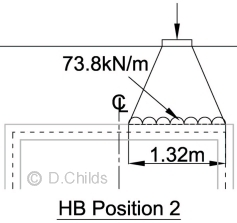
Position 1:
Vertical load = 1.32 × 73.8 + 1.0 × 73.8 = 97.4 + 73.8 = 171.2kN
Net moment about the centre-line of the foundation under the base = 97.4 × 0.74 - 73.8 × 0.9 = 5.7kNm
Bearing pressure under base = P/A ± M/Z = (108.6 + 171.2) / 3.1 ± 6 × (40.6 + 5.7) / 3.12 = 90.3 ± 28.9 = 119.2 & 61.4 kN/m2 < 300 ∴ OK.
Position 2:
Vertical load = 1.32 × 73.8 = 97.4kN
Net moment about the centre-line of the foundation under the base = 97.4 × 0.74 = 72.1kNm
Bearing pressure under base = P/A ± M/Z = (108.6 + 97.4) / 3.1 ± 6 × (40.6 + 72.1) / 3.12 = 66.5 ± 70.4 = 136.9 & -3.9 kN/m2
A small uplift is generally considered acceptable when it is produced by short term loading such as traffic loads. Adjust base pressure for uplift condition.
Eccentricity e = M/P = (40.6 + 72.1) / (108.6 + 97.4) = 0.55m
Adjusted base length = L' = 3(0.5L - e) = 3(0.5 × 3.1 - 0.55) = 3.0m
Maximum adjusted pressure = 2P / [3(0.5L - e)] = 2 × (108.6 + 97.4) / 3.0 = 137.3 kN/m < 300 ∴ OK
Reinforcement Design
Comparing the HB load effects from the single load case analysed above, with the envelope of load effects obtained from the moving load spreadsheet (101a), the correct value for the design moments can be obtained.
Combination 1 determined above
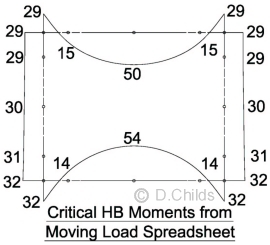
Taking the maximum moments from the results of loading diagrams, and assuming all loading can be mirrored, an envelope is produced. The final design moments can be obtained by adjusting these values by the difference between the single HB case and the moving load spreadsheet results shown above.
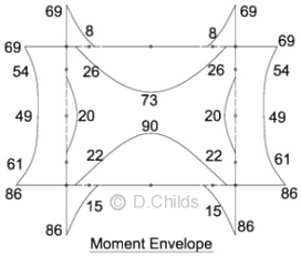
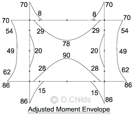
Final Design Moments
Use C32/40 concrete to BS 8500.
Use Grade B500B reinforcement to BS 4449.
BS 8500-1
cl. A.2.1 Table A.1: Assume exposure Class XD2.
cl. A.3: Fixing tolerance for reinforcement Δc = 15mm for insitu concrete.
Table A.5: Nominal cover for C32/40 concrete = 45 + Δc = 60mm with
maximum water-cement ratio = 0.50 and minimum cement content of 340 kg/m3.
BS 5400 Pt 4
The reinforcement requirements can be determined by following the procedure in the 'Reinforced Concrete Deck' example or by using a simple spreadsheet.
The maximum ultimate moment from Diagram A/3a = 90 kNm/m (producing tension in the top face of the floor slab).
This moment consists of 36kNm from dead load and 54kNm from live load.
An approximation of the serviceability moment = 36 / (1.1 × 1.2) + 54 / (1.1 × 1.3) = 27 + 38 = 65 kNm
Live Load Moment / Dead Load Moment = Mq / Mg = 38 / 27 = 1.4
Using spreadsheet 303 suitable reinforcement for a 300mm thick slab is 16mm dia. reinforcement at 125mm centres (Mult = 147kNm, Msls = 84kNm).
Shear
Shear is considered at a distance d away from the support. Nodes on the plane frame model were positioned at these points.
Worst shear in floor slab at nodes 14 and 16 in Combination 1 is 62kN from dead load and 90kN from live load = 152kN
Spreadsheet 303 shows 16mm dia. reinforcement at 125mm centres (As = 1608mm2/m) has a shear resistance of 184kN.
Note: BS 5400 Pt 4 does not specify that shear enhancement for locations close to a support may be used in slabs.
As the critical sections (d from support) are close to points of contraflexure then tension can occur both on the inside and outside faces of the structure. The longitudinal tensile steel to resist shear should therefore be provided on both faces.
A similar procedure is carried out for the walls and roof slab to determine the reinforcement requirements to resist bending and shear.
Axial loads in the walls can be checked using BS 5400 Pt. 4 Clause 5.6.1.1
Maximum axial load in wall = 85kN dead load and 125kN live load = 210kN
0.1 × fcu × Ac = 0.1 × 40 × 300 × 1000 × 10-3 = 1200kN > 210kN ∴ bending can be designed using the procedure for a slab.
As there are no joints in the structure (as recommended in BD 31/01 Clause 4.2.4(c)) then it is important to check for early thermal crack control considering:
- The floor slab being cast onto blinding
- The walls being cast onto the floor slab
- The roof slab being cast onto the walls
This can be achieved by using spreadsheet 306. Although this is for Eurocode design it does incorporate the latest research findings. Alternatively spreadsheet 302 can be used in accordance with BD 28/87, but this does tend to underestimate the reinforcement requirements compared with the latest guidance in Report C660.
Back to Buried Box Structure Tutorial | Back to Tutorial Index
Contact David Childs

David Childs
B.Sc, C.Eng, MICE
Last Updated: 28/01/2020