
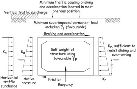
Buried Box Design Example to BS EN 1997-1
and PD 6694-1:2011
The following example is not a definitive solution for the design of a box culvert, but provides one solution to demonstrate the principles involved when considering design standards PD 6694-1:2011 and BS EN 1997-1. The example is presented to promote comment and discussion.
Index
1) Brief
2) Loading
3) Analysis
4) Load Case Tables B.1 B.2 B.3 B.4 B.5 B.6
5) Reinforcement Design
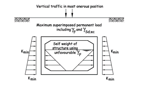
Brief
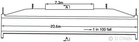
Design the in-situ concrete culvert shown below to carry LM1 and LM3 vehicle SV196. Analyse the culvert using a unit strip method. The bridge site is located south east of Oxford (to establish the range of shade air temperatures).
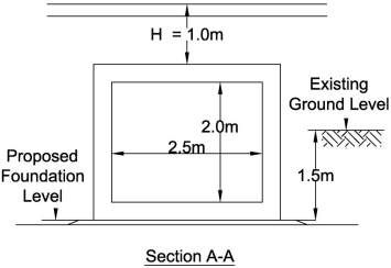
The ground investigation report shows the founding strata to be a well-drained cohesionless soil having an angle of shearing resistance (φ') = 32° and classified as 'not hard' material. Density of the foundation material is 19kN/m3.
Maximum height of ground water is 1m above the invert level of the culvert.
Maximum height of water inside the culvert is 1.8m above the invert level of the culvert.
Proposed foundation level is 1.5m below existing ground level.
Backfill material will be Class 6N with a density (γ) = 19kN/m3.
Take the angle of shearing resistance for Class 6N backfill as φ' = 35°
Fill over the culvert consists of 0.5m of Class 6N overlaid with 0.3m of road sub-base with a density (γ) = 20kN/m3 and 0.2m of carriageway construction with a density (γ) = 24kN/m3
The initial design will be based on using C32/40 concrete to BS 8500 and Grade B500B reinforcement to BS 4449.
Loading
Consider loading on 1m strip of the culvert.
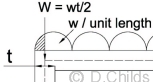
- Self Weight
Assume a wall thickness of 300mm and concrete density (γ) = 25kN/m3
Nominal total load = 25 × [(3.1 × 2.6) - (2.5 × 2.0)] = 76.5kN
- Fill Over Box
Nominal load per metre = 19 × 0.5 + 20 × 0.3 = 15.5kN/m
- Road Construction
Consider the top 200mm as road construction.
Nominal load per metre = 24 × 0.2 = 4.8kN/m
- Settlement
The MCHW Specification Series 600 ensures that any soft spots are removed from the foundation and replaced with suitable material. This will ensure that any differential settlement for a relatively short span box will be negligible. Also a suitable factor of safety will be applied to the allowable bearing pressure when checking the maximum bearing pressure under the box to ensure that settlement will be minimal.
- Load Model 1: UDL + Tandem Systems
Number of notional lanes = n1 = Int(w/3) = Int(7.3/3) = 2
Notional Lane Width = 3.0m
Width of remaining area = 7.3 - 2 × 3.0 = 1.3m
UDL in Lane 1 = αq1q1k = 0.61 × 9 = 5.5kN/m2
UDL in Lane 2 = αq2q2k = 2.2 × 2.5 =5.5kN/m2
UDL in remaining area = αqrqrk = 2.2 × 2.5 = 5.5kN/m2
TS in Lane 1 = Q1k = 300kN
TS in Lane 2 = Q2k = 200kN
Contact patch area = 400 × 400mm
Dispersed area on top of box = 400 + 2 × 1000 × tan30° = 1555 × 1555mm
Edge of carriageway to headwall at end of structure ≈ 6.1m > (1000 × tan30° + 300 / 2) = 727mm.
Also there are no longitudinal joints in the structure, hence full dispersal can be considered.
Transverse Dispersal:
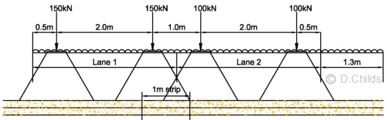
From PD 6694-1:2011 Figure 11.Load per metre where dispersion zones overlap = bW1/L1 + aW2/L2 = 1 × 150 / 1.555 + (1.555 - 1.0) × 100 / 1.555 = 132.2kN/m
Longitudinal Dispersal:
Dispersal zone width for each axle = 1.555m
Patch load for each axle = 132.2 / 1.555 = 85.0kN/m
- Horizontal Surcharge Model for LM1, LM2 & LM3
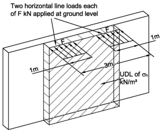
Horizontal line load F = 330KdDf where Kd = Ka or K0 and Df = 1.
Reduction factor = (1 - Hc / 2)2 = (1 - 1 / 2)2 = 0.25
Two line loads are applied so for a 3m lane width the load on a 1m wide strip = 2 × 0.25 × 330Kd / 3 = 55KdkN.
Ka or K0 are obtained from the appropriate load case Table in Annex B.
UDL for LM1 & LM2 = 20KdR = 20Kd (kN/m2)
UDL for LM3 = 30KdR = 30Kd (kN/m2)
- Load Model 2
Wheel load = 200kN
Contact patch area = 400 × 400mm
Wheel spacing on axle = 2.0m ∴ dispersal zones do not overlap (see Figure 11 diagram above).
Longitudinal and Transverse dispersal of wheel load = 400 + 2 × 1000 × tan30° = 1555 × 1555mm
Patch load for each wheel = 200 / 1.5552 = 83.25kN/m
- Load Model 3: SV196 Vehicle
Axle 1 load = 100kN Dynamic Amplification Factor = 1.2 Wheel Load = 1.2 × 50 = 60kN
Axles 2 & 3 loads = 180kN Dynamic Amplification Factor = 1.1 Wheel Load = 1.1 × 90 = 99kN
Trailer Axle loads = 165kN Dynamic Amplification Factor = 1.12 Wheel Load = 1.12 × 82.5 = 92.4kN
Contact patch area = 350 × 350mm
Longitudinal and Transverse dispersal of wheel load = 350 + 2 × 1000 × tan30° = 1505 × 1505mm
Wheel spacing on axles = 2.65m
Loading in Lane 2 is taken as the Frequent loading from LM1 (gr.5 combination)
Frequent Value of Tandem System = ψ1 × Q2k × αQ2
TS in Lane 2 = Q2k = 200kN
Frequent value of wheel load = 0.75 × 100 × 1.0 = 75kN
Longitudinal and Transverse dispersal of TS2 wheel load = 400 + 2 × 1000 × tan30° = 1555 × 1555mm
Transverse Dispersal:
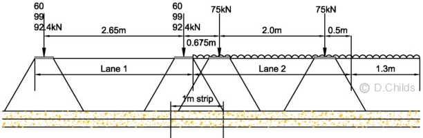
Dispersal zones of adjacent SV and TS wheels overlap (see diagram above).
Consider 1m strip as shown then:
Patch load from SV196 Axle 1 = 60 / 1.5052 = 26.5kN/m2
Patch load from SV196 Axle 2 = 99 / 1.5052 = 43.7kN/m2
Patch load from SV196 Trailer Axle = 92.4 / 1.5052 = 40.8kN/m2
Patch load from TS2 Axle = (1.555 - 0.7) × 75 / 1.5552 = 26.5kN/m2
These patch loads are traversed across the structure at the appropriate axle spacings to obtain the worst effects.
- Critical Traffic Load
A spreadsheet is available from this website to analyse the moving load effects from the LM1, LM2 and LM3 traffic.
The results from the spreadsheet show that the critical load effects (bending moments and shear) are obtained under LM1 traffic.
- Temperature Load
From NA to BS EN 1991-1-5:2003 Clause NA.2.2.1(b):
Span to width ratio = Xclear / LT = 2.5 / 20.6 = 0.12 (<0.2)
Cover (fill + surfacing) = 1.0 > 0.6m
Therefore the structure may be considered to be protected from climatic and operational temperature changes and temperature effects need not be considered for sections under the carriageway.
A spreadsheet has been developed to analyse temperature effects in a box structure should it be required.
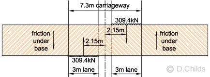
- Braking and Acceleration Forces to PD 6694-1:2011 Clause 10.2.8.2
Hc < LL ∴ the effects of braking and acceleration need to be considered.
For LM1: Qlk = 0.6αQ1(2Q1k) + 0.1αq1q1kw1L
180αQ1 ≤ Qlk ≤ 900kN
αQ1 = αq1 = 1
Q1k = 300 kN
q1k = 9 kN/m
Lane width w1 = 3m
L = 3.1m
Earth cover 0.6m < Hc < LL
Reduction Factor η = (LL - Hc) / (LL - 0,6) = (3.1 - 1.0) / (3.1 - 0.6) = 0.84
Hence Qlk = 0.84 × (360 + 8.37) = 309.4kN
PD 6694 says Qlk should be applied directly to the top of the roof of the structure over a notional lane width, but may be assumed to be distributed structurally over a length of Lj provided account is taken of the tendency for plan rotation.
Taking an extreme condition with braking/acceleration in each lane at maximum eccentricity from the centre of the carriageway then:
Rotation moment = 2 × 309.4 × 2.15 = 1330kNm
Assume rotation resisted by friction under the base then:
Approximate volume of road construction = 7.3 × 3.1 × 0.2 = 5m3
Approximate volume of sub-base = 7.3 × 3.1 × 0.3 = 7m3
Approximate volume of 6N fill over box assuming 1:3 embankment slopes = (20.6 - 3) × 1.0 × 3.1 - (5 + 7) = 43m3
Nominal weight of box and fill over = 76.5 × 20.6 + 3 × 24 + 7 × 20 + 43 × 19 = 2605kN
Under SLS limit state γF and γM = 1.0 so:
Friction force available under each half of box = 2605 / 2 × tan 32° = 814kN
Friction moment available for resisting rotation = 2 × 814 × 20.6 / 4 = 8384kNm ≫ 1330kNm ∴ OK.
No allowance has been made for the earth pressures on the side of the box in this over-simplified calculation; a net resistance of at-rest pressure less active pressure (K0 - Ka) could also be considered. However the calculation justifies adopting the allowance for the in-plane rigidity of the roof and walls of in-situ box in PD 6694-1:2011 Clause 10.2.8.2 by distributing the braking/acceleration force over Lj, and as there are no joints, Lj = 20.6m
Braking/acceleration force = 309.4 / 20.6 = 15kN/m
For LM3: Qlk,s = δω
δ = 0.25 for SV196 vehicle
ω = Basic Axle Loads = 100kN, 180kN & 165kN
Qlk,s (axle 1) = 0.25 × 100kN = 25kN
Qlk,s (axles 2 & 3) = 0.25 × 180kN = 45kN
Qlk,s (axles 4 to 12) = 0.25 × 165kN = 41.25kN
The maximum vertical load that can be positioned over the box is from the trailer axles. Position the edge of the dispersed axle load zone from the leading trailer axle at the edge of the culvert.
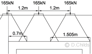 Maximum vertical load from LM3 on a unit width of box = 40.8 × (2 × 1.505 + 0.7) = 151.4kN.
PD 6694-1:2011 Clause 10.2.8.2 says: “The total braking or acceleration force applied to the top of the roof of a buried structure need not be taken as greater than the friction force that can be generated between the earth and the roof.”
Vertical load from fill above culvert = (15.5 + 4.8) × 3.1 = 62.9kN
Assuming a coefficient of friction of tan30° then:
Maximum friction that can be generated on a metre width between the earth and the roof is (151.4 + 62.9)tan30° = 124kN
Total braking force generated by SV196 vehicle = 25 + 2 × 45 + 9 × 41.25 = 486kN
Using the in-plane rigidity of the roof and walls as proven above then braking/acceleration force = 486 / 20.6 = 24kN/m < 124kN ∴ use 24kN/m
- Centrifugal & Other Transverse Forces
Assuming a straight carriageway over the structure then there will be no centrifugal forces acting.
Other transverse forces are taken as 50% of the longitudinal braking force = 50% × 486kN = 243kN
This force will need to be transmitted from the roof slab to the walls; the continuity reinforcement between the two members will need to resist a shearing force of 243 / 20.6 = 12kN/m
Partial Factors γF (From NA to BS EN 1990:2002+A1:2005)
For SLS factors see Clause NA.2.3.9
For EQU factors see Table NA.A2.4(A)
For STR/GEO Comb1 factors see Table NA.A2.4(B)
For STR/GEO Comb2 factors see Table NA.A2.4(C)
PD 6694-1:2011 Clause 10.2.2: Model Factor for negative arching effects for structures not founded on hard material = γSd;ec,max = 1.15 + 0.35(Hc - 8)/3 but not less than 1.15
γSd;ec,max = 1.15 + 0.35(1.0 - 8)/3 = 0.33 < 1.15 ∴ = 1.15
Allow for deviation of road construction thickness to UK NA 1991-1-1 Table NA.1 cl.5.2.3(3) = +55% or -40%.
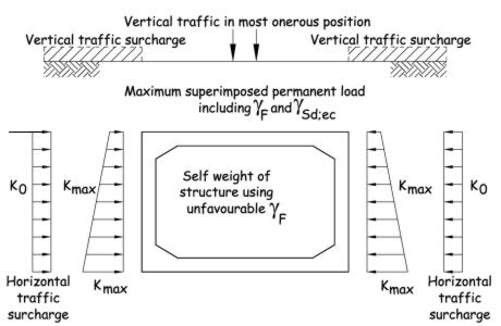
| Unfavourable | SLS | EQU | STR/GEO Comb1 | STR/GEO Comb2 |
| Self weight of structure & backfill γG;sup | 1.0 | 1.05 | 1.35 | 1.0 |
| Superimposed permanent load γG;sup | 1.0 | 1.05 | 1.2 | 1.0 |
| Road traffic action on box γQ;sup | 1.0 | 1.35 | 1.35 | 1.15 |
| Thermal Actions γQ;sup | 1.0 | 1.55 | 1.55 | 1.3 |
| Material Factor to φ' γM | 1.0 | 1.1 | 1.0 | 1.25 |
| Vertical and horizontal water pressures γG;sup | 0.0 | 1.0 | 1.0 | 1.0 |
| Favourable | SLS | EQU | STR/GEO Comb1) | STR/GEO Comb2 |
| Self weight of structure & backfill γG;inf | 1.0 | 0.95 | 0.95 | 1.0 |
| Superimposed permanent load γG;inf | 1.0 | 0.95 | 0.95 | 1.0 |
Analysis
An efficient method of analysis is to use a plane frame model; a spreadsheet is available from this website.
Using C32/40 concrete then the short-term modulus of elasticity Ecm = 22[ (fck + 8) / 10]0.3 = 33kN/mm2.
For analysing permanent loads then it is usual to use the long-term value for Ecm which can be taken as half the short-term value = 33 / 2 = 17kN/mm2.
Shear is considered at a distance d (effective depth of cross-section) away from the support. Nodes (2, 4, 6, 8, 10, 12, 14 & 16) are positioned on the plane frame model at these points to determine the appropriate shear value. An estimate of the concrete cover and reinforcement bar size will be required to determine a value for d. For the example assume member thickness = 300mm, bar size = 20mm and cover = 60mm
Then d = 300 - 60 - 10 = 230mm.
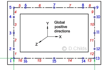
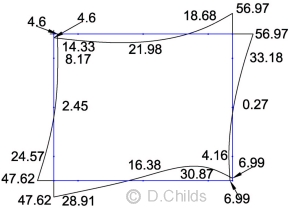
Artificial supports need to be provided to the model at nodes 1 and 13. Node 1 is fixed in the X & Y directions and free to rotate. Node 13 is fixed in the Y direction only. When loading (which includes bearing pressure) is applied to the model then the net reactions at the supports should be zero.
It is usual to analyse the structure using nominal loads for each action and then combine the design values using the appropriate partial factors.
D1) Self Weight Analysis
Assuming 300mm thick for walls, roof and floor then load = 0.3 × 25 = 7.5kN/m
Total load for concrete = 76.5kN
Bearing pressure = 76.5 / 3.1 = 24.7kN/m
The plane frame analysis idealises the structure as a series of beam elements positioned at the centre of the members. Consequently the model dimensions of the culvert are 2.8m wide × 2.3m high. Equilibrium will be maintained in the model by determining the bearing pressure on the model base length of 2.8m. The pressure applied to the model = 76.5 / 2.8 = 27.32kN/m
The bearing pressure can therefore be applied (upwards) as a UDL of 27.32kN/m to the floor members.
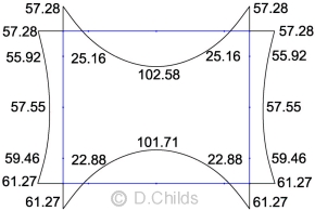
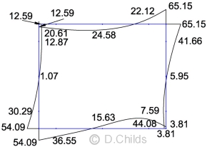
The bending moment results under self weight are shown. Values are displayed on the tension face of the member.
Note: If the correct loading and bearing pressure has been applied to the model then the model reactions at nodes 1 and 13 should be zero.
(D1) Self Weight Moments
D2) Road Construction Analysis
200mm thick surfacing weight = 4.8kN/m applied as UDL to roof members.
However the loading is applied to the outside dimensions (3.1m wide × 2.6m high). A correction can be made by applying point loads at the corners of the model to represent the load outside the centre-line of the corner member.
Point load corrections applied at each corner = 0.15 × 4.8 = 0.72kN
Bearing pressure = 4.8kN/m. UDL applied to floor members = 4.8 × 3.1 / 2.8 = 5.31kN/m2.
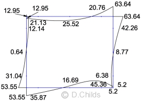
The bending moment results under road construction weight are shown. Values are displayed on the tension face of the member.
(D2) Road Construction Moments
D3) Fill Over Box Analysis
800mm thick fill weight = 15.5kN/m applied as UDL to roof members.
The analysis is similar to the road construction so the results can be multiplied by 15.5 / 4.8 = 3.23 to obtain fill over results.
(D3) Fill Over Box Moments
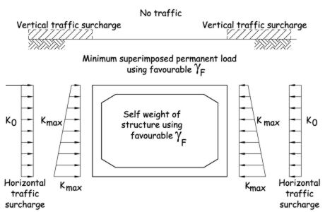
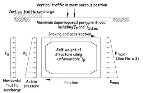
D4, D5 & D6) Earth Pressure on Box Walls Analysis
The earth pressure to the side walls comprises pressure from the backfill between foundation level up to top-of-roof level, and surcharge from the soil/carriageway construction above roof level.
These pressures are modelled as trapezoidal loads for the backfill and a UDL for the surcharge, together with the point load corrections representing the pressure beyond the centre-line of the roof and floor slabs.
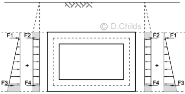
Earth Pressures on Walls Moments
The vertical pressure at top-of-roof level from the carriageway and fill = 4.8 + 15.5 = 20.3 kN/m (per metre width of box).
Surcharge pressure on walls = 20.3 × Kd kN/m.
Point load corrections F2 = F4 = 0.15 × 20.3 × Kd = 3.05 × Kd kN.
Use Kd = 0.6 (Table B.1 SLS Kmax) then:
UDL = 20.3 × 0.6 = 12.18kN/m
F2 = F4 = 3.05 × 0.6 = 1.83kN
The bending moment results under earth surcharge pressures on walls for road construction and fill can be obtained separately by factoring the results.
Road construction surcharge moment factor = 4.8 / 20.3 = 0.236
Fill surcharge moment factor = 15.5 / 20.3 = 0.764
Values are displayed on the tension face of the member.
(D4) Moments from Road Construction Surcharge Pressures
(D5) Moments from Fill Surcharge Pressures
Use Kd = 0.6 (Table B.1 SLS Kmax) then:
The backfill pressure varies from 0 at the top-of-roof level down to Kd × γb'fill × H = 0.6 × 19 × 2.6 = 29.64kN/m at foundation level.
Pressure at centre-line of roof slab = 0.6 × 19 × 0.15 = 1.71kN/m.
Pressure at centre-line of floor slab = 0.6 × 19 × 2.45 = 27.93kN/m.
Point load correction F1 = 0.5 × 1.71 × 0.15 = 0.13kN.
Point load correction F3 = 0.5 × (27.93 + 29.64) × 0.15 = 4.32kN.
The bending moment results under earth backfill pressures on walls are shown. Values are displayed on the tension face of the member.
(D6) Earth Backfill Pressures on Walls Moments
D7) Vertical Traffic Loading Analysis
The moving load spreadsheet shows that LM1 traffic is critical. When moving loads are analysed an envelope of moments (together with shears and axial loads) are produced for the maximum load effect at each node as the vehicle crosses the structure.
The bending moment results from the spreadsheet are shown. Values are displayed on the tension face of the member.
(D7) LM1 Envelope of Maximum Moments
D8) Horizontal Traffic Surcharge Analysis
Horizontal Line Load F = 55KdkN (see above).
UDL for LM1 = 20KdR = 20Kd (kN/m2)
Use Kd = 0.5 (Table B.1 SLS K0) then:
F = 55 × 0.5 = 27.5kN
UDL = 20 × 0.5 = 10kN/m
Point load correction F2 = F4 = 10 × 0.15 = 1.5kN.
The bending moment results from the spreadsheet are shown. Values are displayed on the tension face of the member.
(D8) LM1 Surcharge Pressures on Walls Moments
Load Case Table B.1
The bending moments for actions shown in Table B.1 are obtained by applying the appropriate partial factors to the moment values obtained from the plane frame analysis results.
The maximum load effects in the members will be obtained with no water inside the culvert.
A simple spreadsheet was set up to combine the factored moments for the Limit States SLS, EQU, STR/GEO Combination 1 and STR/GEO Combination 2. The results are shown below.
| Diagram | SLS | EQU | STR/GEO Comb1 | STR/GEO Comb2 |
| D1 | 1.0 | 1.05 | 1.35 | 1.0 |
| D2 | 1.0 × 1.15 × 1.55 = 1.78 | 1.05 × 1.15 × 1.55 = 1.87 | 1.2 × 1.15 × 1.55 = 2.14 | 1.0 × 1.15 × 1.55 = 1.78 |
| D3 | 1.0 × 1.15 = 1.15 | 1.05 × 1.15 = 1.21 | 1.2 × 1.15 = 1.38 | 1.0 × 1.15 = 1.15 |
| D4 | 1.0 × 1.55 × 0.6 / 0.6 = 1.55 | 1.05 × 1.55 × 0.77 / 0.6 = 2.09 | 1.35 × 1.55 × 0.72 / 0.6 = 2.51 | 1.0 × 1.55 × 0.84 / 0.6 = 2.17 |
| D5 | 1.0 × 0.6 / 0.6 = 1.0 | 1.05 × 0.77 / 0.6 = 1.35 | 1.35 × 0.72 / 0.6 = 1.62 | 1.0 × 0.84 / 0.6 = 1.40 |
| D6 | 1.0 × 0.6 / 0.6 = 1.0 | 1.05 × 0.77 / 0.6 = 1.35 | 1.35 × 0.72 / 0.6 = 1.62 | 1.0 × 0.84 / 0.6 = 1.40 |
| D7 | 1.0 | 1.35 | 1.35 | 1.15 |
| D8 | 1.0 × 0.5 / 0.5 = 1.0 | 1.35 × 0.54 / 0.5 = 1.46 | 1.35 × 0.5 / 0.5 = 1.35 | 1.15 × 0.58 / 0.5 = 1.33 |
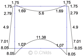
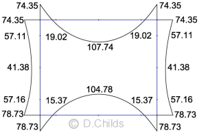
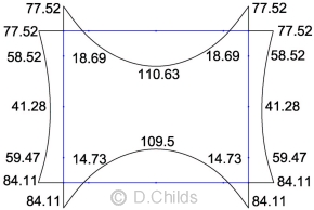
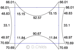
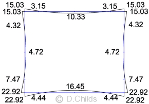
Limit State Results for Table B.1 Loading:
SLS Moments
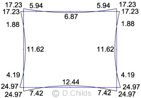
EQU Moments
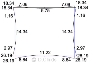
STR/GEO Comb.1 Moments
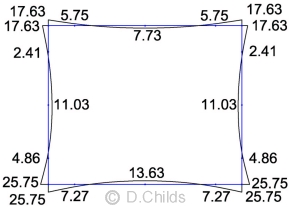
STR/GEO Comb.2 Moments
Load Case Table B.2
The bending moments for actions shown in Table B.2 are obtained by applying the appropriate partial factors to the moment values obtained from the plane frame analysis results.
The maximum load effects in the members will be obtained with no water inside the culvert.
A simple spreadsheet was set up to combine the factored moments for the Limit States SLS, EQU, STR/GEO Combination 1 and STR/GEO Combination 2. The results are shown below.
| Diagram | SLS | EQU | STR/GEO Comb1 | STR/GEO Comb2 |
| D1 | 1.0 | 0.95 | 0.95 | 1.0 |
| D2 | 1.0 × 0.6 = 0.6 | 0.95 × 0.6 = 0.57 | 0.95 × 0.6 = 0.57 | 1.0 × 0.6 = 0.6 |
| D3 | 1.0 | 0.95 | 0.95 | 1.0 |
| D4 | 1.0 × 0.6 × 0.6 / 0.6 = 0.6 | 1.05 × 0.6 × 0.77 / 0.6 = 0.81 | 1.35 × 0.6 × 0.72 / 0.6 = 0.97 | 1.0 × 0.6 × 0.84 / 0.6 =0.84 |
| D5 | 1.0 × 0.6 / 0.6 = 1.0 | 1.05 × 0.77 / 0.6 = 1.35 | 1.35 × 0.72 / 0.6 = 1.62 | 1.0 × 0.84 / 0.6 = 1.40 |
| D6 | 1.0 × 0.6 / 0.6 = 1.0 | 1.05 × 0.77 / 0.6 = 1.35 | 1.35 × 0.72 / 0.6 = 1.62 | 1.0 × 0.84 / 0.6 = 1.40 |
| D7 | 0 | 0 | 0 | 0 |
| D8 | 1.0 × 0.5 / 0.5 = 1.0 | 1.35 × 0.54 / 0.5 = 1.46 | 1.35 × 0.5 / 0.5 = 1.35 | 1.15 × 0.58 / 0.5 = 1.33 |
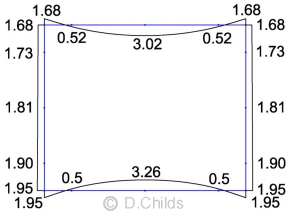
Limit State Results for Table B.2 Loading:
SLS Moments
EQU Moments
STR/GEO Comb.1 Moments
STR/GEO Comb.2 Moments
Load Case Table B.3
The bending moments for actions shown in Table B.3 are obtained by applying the appropriate partial factors to the moment values obtained from the plane frame analysis results.
Two conditions will be analysed:
- with water inside the culvert
- with no water inside the culvert
Depth of water = 1.8m so pressure on wall at base = 1.8 × 10 = 18kN/m
Pressure from water on pane frame model floor slab = 18 × 2.5 / 2.8 = 16.07kN/m
Bearing pressure from water = 18 × 2.5 / 3.1 = 14.52kN/m
Triangular loads are applied to the walls of the plane frame model, the UDLs of 16.07kN/m on the floor slab representing the water pressure and bearing pressure will cancel out.
The results from the plane frame analysis are included in the combination with the appropriate partial factors. Note that the water pressure on the walls has been applied to members 1 to 3 and 10 to 12 for convenience; this has slightly overestimated the depth (1.92m instead of 1.8m). However the load effects are not great and can be considered acceptable.
The maximum load effects in the members will be obtained by comparing the results.
A simple spreadsheet was set up to combine the factored moments for the Limit States SLS, EQU, STR/GEO Combination 1 and STR/GEO Combination 2. The results are shown below.
| Diagram | SLS | EQU | STR/GEO Comb1 | STR/GEO Comb2 |
| D1 | 1.0 | 1.05 | 1.35 | 1.0 |
| D2 | 1.0 × 1.15 × 1.55 = 1.78 | 1.05 × 1.15 × 1.55 = 1.87 | 1.2 × 1.15 × 1.55 = 2.14 | 1.0 × 1.15 × 1.55 = 1.78 |
| D3 | 1.0 × 1.15 = 1.15 | 1.05 × 1.15 = 1.21 | 1.2 × 1.15 = 1.38 | 1.0 × 1.15 = 1.15 |
| D4 | 1.0 × 1.55 × 0.2 / 0.6 = 0.52 | 0.95 × 1.55 × 0.18 / 0.6 = 0.44 | 0.95 × 1.55 × 0.2 / 0.6 = 0.49 | 1.0 × 1.55 × 0.16 / 0.6 = 0.41 |
| D5 | 1.0 × 0.2 / 0.6 = 0.33 | 0.95 × 0.18 / 0.6 = 0.29 | 0.95 × 0.2 / 0.6 = 0.32 | 1.0 × 0.16 / 0.6 = 0.27 |
| D6 | 1.0 × 0.2 / 0.6 = 0.33 | 0.95 × 0.18 / 0.6 = 0.29 | 0.95 × 0.2 / 0.6 = 0.32 | 1.0 × 0.16 / 0.6 = 0.27 |
| D7 | 1.0 | 1.35 | 1.35 | 1.15 |
| D8 | 0 | 0 | 0 | 0 |
| Water | 0 | 1.0 | 1.0 | 1.0 |
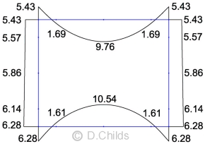
Limit State Results for Table B.3 Loading:
SLS Moments
EQU Moments
STR/GEO Comb.1 Moments
STR/GEO Comb.2 Moments
Load Case Table B.4
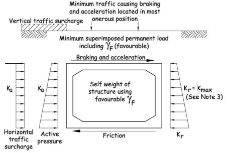
Stability needs to be considered by assessing the resistance to sliding and overturning together with the bearing pressure to PD 6694-1:2011 Clauses 10.3.2 and 10.3.3.
Load effects in the members will need to be considered if Kmax has to be increased above the values given in PD 6694-1:2011 Table B.4.
Partial Factors can be determined as before.
Consider horizontal forces to check sliding:
For drained conditions design resistance to sliding Rd = V'd tan δd where δ = structure-ground interface friction angle = 32°
Applying γM to tanδ we get δd = tan-1(tanδ / γM)
SLS: δd = tan-1(tan32 / 1.0) = 32°
EQU: δd = tan-1(tan32 / 1.1) = 29.6°
ULS Comb.1: δd = tan-1(tan32 / 1.0) = 32°
ULS Comb.2: δd = tan-1(tan32 / 1.25) = 26.6°
Sliding at SLS:
- γF = 1.0 for all elements.
- Maximum surcharge from road construction = 1.55 × 4.8 = 7.44kN/m
- Maximum surcharge from fill above roof level = 15.5kN/m
- Active force from surcharge = 0.33 × (7.44 + 15.5) × 2.6 = 19.68kN
- Passive force from surcharge = 0.6 × (7.44 + 15.5) × 2.6 = 35.79kN
- Backfill pressure at foundation level = 19 × 2.6 = 49.4kN/m2
- Active force from backfill up to roof = 0.33 × 49.4 × 2.6 / 2 = 21.19kN
- Passive force from backfill up to roof = 0.6 × 49.4 × 2.6 / 2 = 38.53kN
- Active force from traffic surcharge line load = 0.33 × 55 = 18.15kN
- Active force from LM1 traffic UDL surcharge = 0.33 × 20 × 2.6 = 17.16kN
- Active force from LM3 traffic UDL surcharge = 0.33 × 30 × 2.6 = 25.74kN
- Braking and acceleration force for LM1 traffic = 15kN
- Braking and acceleration force for LM3 traffic = 24kN
- Total active force with LM3 traffic = 19.68 +21.19 + 18.15 + 25.74 + 24 = 108.76kN
- Total passive force = 35.79 + 38.53 = 74.32kN
- Active force > Passive force ∴ friction under the base is required to stop sliding.
- Vertical load on foundation:
- Road construction = 1.15 × 1.55 × 4.8 × 3.1 = 26.53kN
- Fill on roof = 1.15 × 15.5 × 3.1 = 55.26kN
- Self weight of concrete = 76.5kN
- LM1 traffic UDL = 5.5 × 3.1 = 17.05kN
- LM1 traffic Tandem System = 85.0 × 1.555 × 2 = 264kN
- LM3 traffic = 40.8 × (2 × 1.505 + 0.7) = 151kN
- By inspection LM3 traffic critical (maximum horizontal with minimum vertical loading).
- V'd = 26.53 + 55.26 + 76.5 + 151 = 309.29kN
- Maximum Rd = 309.29 × tan32° = 193kN
- Friction required = 108.76 - 74.32 = 34.44 < 193 ∴ sliding can be resisted using Kmax = 0.6 ∴ OK.
Sliding at EQU:
- Active force from surcharge = 0.44 × 1.05 × (7.44 + 15.5) × 2.6 = 27.56kN
- Passive force from surcharge = 0.6 × 1.05 ×(7.44 + 15.5) × 2.6 = 37.58kN
- Active force from backfill up to roof = 0.44 × 1.05 × 49.4 × 2.6 / 2 = 29.67kN
- Passive force from backfill up to roof = 0.6 × 1.05 × 49.4 × 2.6 / 2 = 40.46kN
- Active force from traffic surcharge line load = 0.37 × 1.35 × 55 = 27.47kN
- Active force from LM3 traffic UDL surcharge = 0.37 × 1.35 × 30 × 2.6 = 38.96kN
- Braking and acceleration force for LM3 traffic = 1.35 × 24 = 32.4kN
- Total active force with LM3 traffic = 27.56 + 29.67 + 27.47 + 38.96 + 32.4 = 156.06kN
- Total passive force = 37.58 + 40.46 = 78.04kN
- Active force > Passive force ∴ friction under the base is required to stop sliding.
- Vertical load on foundation:
- Road construction = 1.05 × 26.53 = 27.86kN
- Fill on roof = 1.05 × 55.26 = 58.02kN
- Self weight of concrete = 1.05 × 76.5 = 80.33kN
- LM3 traffic = 1.35 × 151 = 204kN
- V'd = 27.86 + 58.02 + 80.33 + 204 = 370kN
- Maximum Rd = 370 × tan29.6° = 210kN
- Friction required = 156.06 - 78.04 = 78.02 < 210 ∴ sliding can be resisted using Kmax = 0.6 ∴ OK.
Sliding at ULS comb.1:
- Active force from surcharge = 0.40 × 1.20 × (7.44 + 15.5) × 2.6 = 28.63kN
- Passive force from surcharge = 0.72 × 1.20 ×(7.44 + 15.5) × 2.6 = 51.53kN
- Active force from backfill up to roof = 0.40 × 1.35 × 49.4 × 2.6 / 2 = 34.68kN
- Passive force from backfill up to roof = 0.72 × 1.35 × 49.4 × 2.6 / 2 = 62.42kN
- Active force from traffic surcharge line load = 0.33 × 1.35 × 55 = 24.5kN
- Active force from LM3 traffic UDL surcharge = 0.33 × 1.35 × 30 × 2.6 = 34.75kN
- Braking and acceleration force for LM3 traffic = 1.35 × 24 = 32.4kN
- Total active force with LM3 traffic = 28.63 + 34.68 + 24.5 + 34.75 + 32.4 = 154.96kN
- Total passive force = 51.53 + 62.42 = 113.95kN
- Active force > Passive force ∴ friction under the base is required to stop sliding.
- Vertical load on foundation:
- Road construction = 1.20 × 26.53 = 31.84kN
- Fill on roof = 1.20 × 55.26 = 66.31kN
- Self weight of concrete = 1.35 × 76.5 = 103.28kN
- LM3 traffic = 1.35 × 151 = 204kN
- V'd = 31.84 + 66.31 + 103.28 + 204 = 405kN
- Maximum Rd = 405 × tan32° = 253kN
- Friction required = 154.96 - 113.95 = 41.01 < 253 ∴ sliding can be resisted using Kmax = 0.72 ∴ OK.
Sliding at ULS comb.2
- Active force from surcharge = 0.49 × 1.0 × (7.44 + 15.5) × 2.6 = 29.23kN
- Passive force from surcharge = 0.84 × 1.0 ×(7.44 + 15.5) × 2.6 = 50.1kN
- Active force from backfill up to roof = 0.49 × 1.0 × 49.4 × 2.6 / 2 = 31.47kN
- Passive force from backfill up to roof = 0.84 × 1.0 × 49.4 × 2.6 / 2 = 53.94kN
- Active force from traffic surcharge line load = 0.41 × 1.15 × 55 = 25.93kN
- Active force from LM3 traffic UDL surcharge = 0.41 × 1.15 × 30 × 2.6 = 36.78kN
- Braking and acceleration force for LM3 traffic = 1.15 × 24 = 27.6kN
- Total active force with LM3 traffic = 29.23 + 31.47 + 25.93 + 36.78 + 27.6 = 151.01kN
- Total passive force = 50.1 + 53.94 = 104.04kN
- Active force > Passive force ∴ friction under the base is required to stop sliding.
- Vertical load on foundation:
- Road construction = 1.0 × 26.53 = 26.53kN
- Fill on roof = 1.0 × 55.26 = 55.26kN
- Self weight of concrete = 1.0 × 76.5 = 76.5kN
- LM3 traffic = 1.15 × 151 = 174kN
- V'd = 26.53 + 55.26 + 76.5 + 174 = 332kN
- Maximum Rd = 332 × tan26.6° = 166kN
- Friction required = 151.01 - 104.04 = 46.97 < 166 ∴ sliding can be resisted using Kmax = 0.84 ∴ OK.
Overturning:
Stability against overturning is found by considering the eccentricity of loads about the centre of the foundation.
PD 6694-1 cl. 5.2.2 says it is prudent to ensure that no uplift occurs anywhere under the foundations at SLS (eccentricity to be kept within the middle third of the base length).
BS EN 1997-1 cl. 6.5.4 says that special precautions shall be taken where the eccentricity of loading exceeds 1/3 of the
width of a rectangular footing at ULS (eccentricity to be kept within middle two thirds of base length).
Eccentricity of Traffic Loading:
Maximum vertical traffic loading from trailer axles:
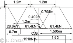
LM3 patch loading on 1m width of roof
Distance to centre of gravity of patch loads = [40.8 × 1.505 × (1.505 + 1.2) + 40.8 × 0.7 × (3.1 - 0.35)] / 151 = 1.62m
As the SV196 trailer has at least 4 axles at 1.2m centres then the patch loads can be moved to form the mirror image of the diagram shown, so the 1.62m can be measured from the front edge or back edge of the culvert.
The eccentricity of the load is therefore ± (1.62 - 3.1 / 2) = ± 0.07m.
Consider SLS bearing pressure under base:
Total vertical load = 26.53 + 55.26 + 151 + 76.5 =309.29kN
Taking moments about the centre of the base (point A in diagram below):
Moment = 2.6 × (18.15 + 24) + 1.3 × (25.74 + 19.68 - 35.79) + 0.867 × (21.19 - 38.53) + 151 × 0.07 = 117.6kNm
Eccentricity e = M / V = 117.6 / 309.29 = 0.38m.
No uplift will occur if e < base length / 6 = 3.1 / 6 = 0.517 > 0.38m ∴ OK.
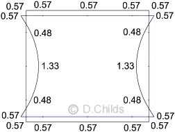
The bearing pressure diagram will be trapezoidal at SLS so pressures = V/A ± M / Z = 309.29 / (1.0 × 3.1) ± 117.6 / (1.0 × 3.12 / 6) = 99.77 ± 73.42 = 173 and 26 kN/m2.
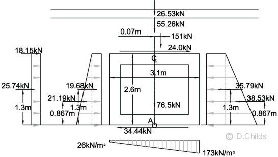
Bearing Pressure under Base at SLS
Check for eccentricity of loads at ULS:
For EQU Limit State:
Total vertical load = 27.86 + 58.02 + 151 × 1.35 + 80.33 = 370.06kN
Taking moments about the centre of the base (point A in diagram below):
Moment = 2.6 × (27.47 + 32.4) + 1.3 × (38.96 + 27.56 - 37.58) + 0.867 × (29.67 - 40.46) + 204 × 0.07 = 198.21kNm
Eccentricity e = M / V = 198.21 / 370.06 = 0.536m.
Check whether eccentricity exceeds base length / 3 = 3.1 / 3 = 1.03 > 0.536m ∴ OK.
The bearing pressure diagram will be rectangular at ULS so pressure = V / (L - 2e) = 370.06 / (3.1 - 2 × 0.536) = 182 kN/m2.
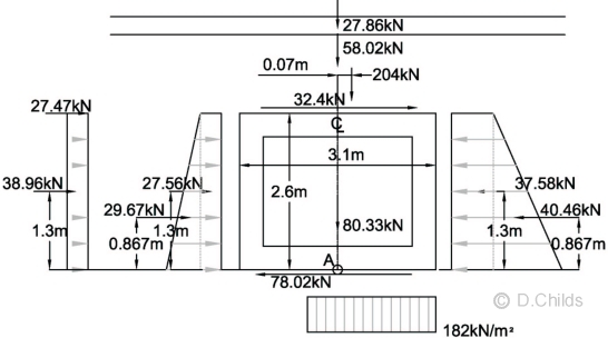
Bearing Pressure under Base at EQU
For STR/GEO (Comb 1) Limit State:
Total vertical load = 31.84 + 66.31 + 151 × 1.35 + 103.28 = 405.28kN
Taking moments about the centre of the base (point A in diagram below):
Moment = 2.6 × (24.5 + 32.4) + 1.3 × (34.75 + 28.63 - 51.53) + 0.867 × (34.68 - 62.42) + 204 × 0.07 = 153.57kNm
Eccentricity e = M / V = 153.57 / 405.28 = 0.379m.
Check whether eccentricity exceeds base length / 3 = 3.1 / 3 = 1.03 > 0.379m ∴ OK.
The bearing pressure diagram will be rectangular at ULS so pressure = V / (L - 2e) = 405.28 / (3.1 - 2 × 0.379) = 173 kN/m2.
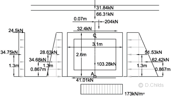
Bearing Pressure under Base at STR/GEO (Comb 1)
For STR/GEO (Comb 2) Limit State:
Total vertical load = 26.53 + 55.26 + 151 × 1.15 + 76.5 = 331.94kN
Taking moments about the centre of the base (point A in diagram below):
Moment = 2.6 × (25.93 + 27.6) + 1.3 × (36.78 + 29.23 - 50.1) + 0.867 × (31.47 - 53.94) + 174 × 0.07 = 152.56kNm
Eccentricity e = M / V = 152.56 / 331.94 = 0.460m.
Check whether eccentricity exceeds base length / 3 = 3.1 / 3 = 1.03 > 0.460m ∴ OK.
The bearing pressure diagram will be rectangular at ULS so pressure = V / (L - 2e) = 331.94 / (3.1 - 2 × 0.46) = 152 kN/m2.
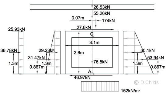
Bearing Pressure under Base at STR/GEO (Comb 2)
Check Bearing Resistance from BS EN 1997-1 Clause D.4
Equation (D.2): R/A' = c'Ncbcscic + q'Nqbqsqiq + 0.5γdB'Nγbγsγiγ
c' = 0 (cohesionless soil)
q' = 1.5 × 19 = 28.5 kN/m2 (overburden pressure)
γ' = 19 kN/m3 (weight density of foundation material)
Nq = eπtanφ'dtan2(45 + φ'd/2)
Nγ = 2 (Nq - 1) tanφ', where δ ≥ φ' / 2 (rough base)
bq = bγ = (1 - αtanφ'd)
Inclination α = 0
sq = 1 + (B' / L') sinφ'd
sγ = 1 - 0.3(B' / L')
m = mB = [2 + (B' / L')] / [1 + (B' / L')] when H acts in the direction of B'
iq = [1 - H / (V + A'c'dcotφ'd)]m
iγ = [1 - H / (V + A'c'dcotφ'd)]m+1
From Figure D.1:
L' = 20.6m (transverse width of foundation)
B = 3.1m B' = B - 2eB
For 1m strip design A' = 1.0 × B' = B'
| SLS | EQU | STR/GEO Comb1 | STR/GEO Comb2 |
|
| eB | 0.38 | 0.536 | 0.379 | 0.46 |
| A' & B' | 3.1 - 2 × 0.38 = 2.224 | 3.1 - 2 × 0.536 = 2.028 | 3.1 - 2 × 0.379 = 2.342 | 3.1 - 2 × 0.46 = 2.18 |
| γd = γ' × γG;inf | 19.0 × 1.0 = 19.0 | 19.0 × 0.95 = 18.05 | 19.0 × 0.95 = 18.05 | 19.0 × 1.0 = 19.0 |
| φ'd | tan-1(tan32 / 1.0) = 32° | tan-1(tan32 / 1.1) = 29.6° | tan-1(tan32 / 1.0) = 32° | tan-1(tan32 / 1.25) = 26.6° |
| Nq | 23.18 | 17.59 | 23.18 | 12.64 |
| Nγ | 27.72 | 18.85 | 27.72 | 11.66 |
| bq & bγ | 1.0 | 1.0 | 1.0 | 1.0 |
| sq | 1.057 | 1.049 | 1.06 | 1.047 |
| sγ | 0.968 | 0.97 | 0.966 | 0.968 |
| m | 1.903 | 1.91 | 1.898 | 1.904 |
| Net Hd | 108.76 - 74.32 = 34.44 | 156.06 - 78.04 = 78.02 | 154.96 - 113.95 = 41.01 | 151.01 - 101.04 = 49.97 |
| Vd | 309.29 | 370.06 | 405.28 | 331.94 |
| iq | 0.799 | 0.636 | 0.817 | 0.733 |
| iγ | 0.71 | 0.502 | 0.734 | 0.623 |
| q'Nqbqsqiq | 558 | 334 | 572 | 276 |
| 0.5γdB'Nγbγsγiγ | 426 | 171 | 422 | 151 |
| R / A' | 984 | 505 | 994 | 427 |
| Vd / A' | 309.29 / 2.224 = 139 | 370.06 / 2.028 = 182 | 405.28 / 2.342 = 173 | 331.94 / 2.18 = 152 |
| R / Vd | 7.08 | 2.77 | 5.75 | 2.81 |
PD 6694-1:2011 Clause 5.2.2 says the serviceability limit state for settlement can be verified by ensuring that a "sufficiently low fraction of the ground strength is mobilized". This requirement can be deemed to be satisfied if the maximum pressure under a foundation at SLS does not exceed one third of the design resistance R/A'.
1/3 (R / A') = 984 / 3 = 328 kN/m2
Maximum bearing pressure at SLS = 173 kN/m2 < 328 ∴ settlement requirement can be deemed to be satisfied.
Minimum Bearing Resistance Factor = 2.77 > 1.0 ∴ O.K.
Load Case Table B.5
This is similar to Table B.4 loading except vertical loads are treated as favourable.
Load effects in the members will need to be considered if Kmax has to be increased above the values given in PD 6694-1:2011 Table B.5.
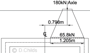
Consider tractor axle in worst position
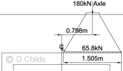
65.8kN LM3 patch loading on 1m width of roof at e = 0.798m
Consider the maximum friction that can be developed between the 180kN axle and the roof of the structure:
Maximum vertical load from LM3 on a unit width of box = 65.8kN.
Vertical load from fill above culvert = (15.5 + 4.8 × 0.6) × 3.1 = 56.98kN
Assuming a coefficient of friction of tan30° then:
Maximum friction that can be generated on a metre width between the earth and the roof is (65.8 + 56.98)tan30° = 71kN
Total braking force generated by SV196 vehicle = 25 + 2 × 45 + 9 × 41.25 = 486kN
Using the in-plane rigidity of the roof and walls as proven above then braking/acceleration force = 486 / 20.6 = 23.6kN/m < 71kN ∴ use 23.6kN/m
Sliding at SLS:
- γF = 1.0 for all elements.
- Minimum surcharge from road construction = 0.6 × 4.8 = 2.88kN/m
- Minimum surcharge from fill above roof level = 15.5kN/m
- Active force from surcharge = 0.33 × (2.88 + 15.5) × 2.6 = 15.77kN
- Passive force from surcharge = 0.6 × (2.88 + 15.5) × 2.6 = 28.67kN
- Backfill pressure at foundation level = 19 × 2.6 = 49.4kN/m2
- Active force from backfill up to roof = 0.33 × 49.4 × 2.6 / 2 = 21.19kN
- Passive force from backfill up to roof = 0.6 × 49.4 × 2.6 / 2 = 38.53kN
- Active force from traffic surcharge line load = 0.33 × 55 = 18.15kN
- Active force from LM3 traffic UDL surcharge = 0.33 × 30 × 2.6 = 25.74kN
- Braking and acceleration force for LM3 traffic = 23.6kN
- Total active force with LM3 traffic = 15.77 +21.19 + 18.15 + 25.74 + 23.6 = 104.45kN
- Total passive force = 28.67 + 38.53 = 67.2kN
- Active force > Passive force ∴ friction under the base is required to stop sliding.
- Vertical load on foundation:
- Road construction = 0.6 × 4.8 × 3.1 = 8.93kN
- Fill on roof = 15.5 × 3.1 = 48.05kN
- Self weight of concrete = 76.5kN
- LM3 traffic = 65.8kN
- V'd = 8.93 + 48.05 + 76.5 + 65.8 = 199.28kN
- Maximum Rd = 199.28 × tan32° = 125kN
- Friction required = 104.85 - 67.2 = 38 < 125 ∴ sliding can be resisted using Kmax = 0.6 ∴ OK.
Sliding at EQU:
- Active force from surcharge = 0.44 × 0.95 × (2.88 + 15.5) × 2.6 = 19.98kN
- Passive force from surcharge = 0.6 × 0.95 ×(2.88 + 15.5) × 2.6 = 27.24kN
- Active force from backfill up to roof = 0.44 × 0.95 × 49.4 × 2.6 / 2 = 26.84kN
- Passive force from backfill up to roof = 0.6 × 0.95 × 49.4 × 2.6 / 2 = 36.61kN
- Active force from traffic surcharge line load = 0.37 × 1.35 × 55 = 27.47kN
- Active force from LM3 traffic UDL surcharge = 0.37 × 1.35 × 30 × 2.6 = 38.96kN
- Braking and acceleration force for LM3 traffic = 1.35 × 23.6 = 31.9kN
- Total active force with LM3 traffic = 19.98 + 26.84 + 27.47 + 38.96 + 31.9 = 145.15kN
- Total passive force = 27.24 + 36.61 = 63.85kN
- Active force > Passive force ∴ friction under the base is required to stop sliding.
- Vertical load on foundation:
- Road construction = 0.95 × 8.93 = 8.48kN
- Fill on roof = 0.95 × 48.05 = 45.65kN
- Self weight of concrete = 0.95 × 76.5 = 72.68kN
- LM3 traffic = 1.35 × 65.8 = 88.83kN
- V'd = 8.48 + 45.65 + 72.68 + 88.83 = 215.64kN
- Maximum Rd = 215.64 × tan29.6° = 123kN
- Friction required = 145.15 - 63.85 = 81 < 123 ∴ sliding can be resisted using Kmax = 0.6 ∴ OK.
Sliding at ULS comb.1:
- Active force from surcharge = 0.40 × 0.95 × (2.88 + 15.5) × 2.6 = 18.16kN
- Passive force from surcharge = 0.72 × 0.95 ×(2.88 + 15.5) × 2.6 = 32.69kN
- Active force from backfill up to roof = 0.40 × 0.95 × 49.4 × 2.6 / 2 = 24.40kN
- Passive force from backfill up to roof = 0.72 × 0.95 × 49.4 × 2.6 / 2 = 43.93kN
- Active force from traffic surcharge line load = 0.33 × 1.35 × 55 = 24.5kN
- Active force from LM3 traffic UDL surcharge = 0.33 × 1.35 × 30 × 2.6 = 34.75kN
- Braking and acceleration force for LM3 traffic = 1.35 × 23.6 = 31.86kN
- Total active force with LM3 traffic = 18.16 + 24.4 + 24.5 + 34.75 + 31.86 = 133.67kN
- Total passive force = 32.69 + 43.93 = 76.62kN
- Active force > Passive force ∴ friction under the base is required to stop sliding.
- Vertical load on foundation:
- Road construction = 0.95 × 8.93 = 8.48kN
- Fill on roof = 0.95 × 48.05 = 45.65kN
- Self weight of concrete = 0.95 × 76.5 = 72.68kN
- LM3 traffic = 1.35 × 65.8 = 88.83kN
- V'd = 8.48 + 45.65 + 72.68 + 88.83 = 215.64kN
- Maximum Rd = 215.64 × tan32° = 135kN
- Friction required = 133.67 - 76.62 = 57 < 135 ∴ sliding can be resisted using Kmax = 0.72 ∴ OK.
Sliding at ULS comb.2
- Active force from surcharge = 0.49 × 1.0 × (2.88 + 15.5) × 2.6 = 23.42kN
- Passive force from surcharge = 0.84 × 1.0 ×(2.88 + 15.5) × 2.6 = 40.14kN
- Active force from backfill up to roof = 0.49 × 1.0 × 49.4 × 2.6 / 2 = 31.47kN
- Passive force from backfill up to roof = 0.84 × 1.0 × 49.4 × 2.6 / 2 = 53.94kN
- Active force from traffic surcharge line load = 0.41 × 1.15 × 55 = 25.93kN
- Active force from LM3 traffic UDL surcharge = 0.41 × 1.15 × 30 × 2.6 = 36.78kN
- Braking and acceleration force for LM3 traffic = 1.15 × 23.6 = 27.14kN
- Total active force with LM3 traffic = 23.42 + 31.47 + 25.93 + 36.78 + 27.14 = 144.7kN
- Total passive force = 40.14 + 53.94 = 94.08kN
- Active force > Passive force ∴ friction under the base is required to stop sliding.
- Vertical load on foundation:
- Road construction = 1.0 × 8.93 = 8.93kN
- Fill on roof = 1.0 × 48.05 = 48.05kN
- Self weight of concrete = 1.0 × 76.5 = 76.5kN
- LM3 traffic = 1.15 × 65.8 = 75.67kN
- V'd = 8.93 + 48.05 + 76.5 + 75.67 = 209.15kN
- Maximum Rd = 209.15 × tan26.6° = 105kN
- Friction required = 144.7 - 94.08 = 51 < 105 ∴ sliding can be resisted using Kmax = 0.84 ∴ OK.
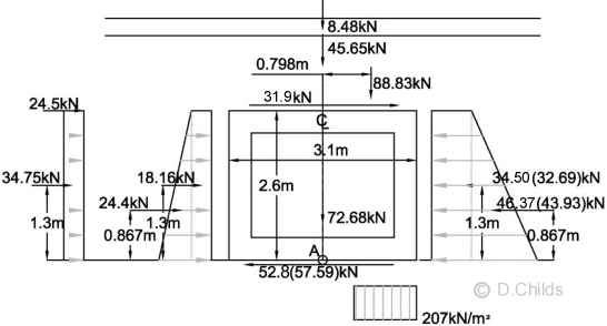
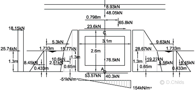
Overturning:
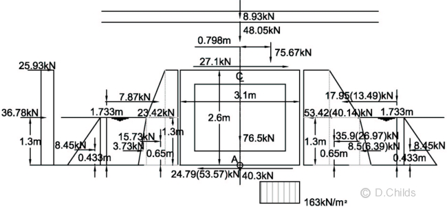
Stability against overturning is found by considering the eccentricity of loads about the centre of the foundation.
Consider SLS bearing pressure under base:
Total vertical load = 8.93 + 48.05 + 65.8 + 76.5 = 199.28kN
Taking moments about the centre of the base (point A in diagram below):
Moment = 2.6 × (18.15 + 23.6) + 1.3 × (25.74 + 15.77 - 28.67) + 0.867 × (21.19 - 38.53) + 65.8 × 0.798 = 162.7kNm
Eccentricity e = M / V = 162.7 / 199.28 = 0.816m.
No uplift will occur if e < base length / 6 = 3.1 / 6 = 0.517 < 0.816m ∴ Fail.
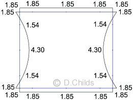
SLS pressures = V/A ± M / Z = 199.28 / (1.0 × 3.1) ± 162.7 / (1.0 × 3.12 / 6) = 64.28 ± 101.58 = 166 and -37 kN/m2.
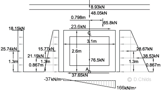
Bearing Pressure under Base at SLS with uplift
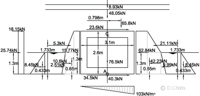
Note 3 in Table B.5 says Kmax may be increased to maintain stability, but check movement.
Active moment = 2.6 × (18.15 + 23.6) + 1.3 × (25.74 + 15.77) + 0.867 × 21.19 + 65.8 × 0.798 = 233.37kNm
Passive moment (with Kmax = 0.6) = 1.3 × 28.67 + 0.867 × 38.53 = 70.68kNm
To avoid uplift V/A - M/Z > 0
So M < V × Z / A = 199.28 × 3.12 / (6 × 3.1) = 102.96kNm
Passive moment required = 233.37 - 102.96 = 130.41kNm
Maximum bearing pressure = 199.28 / 3.1 + 102.96 × 6 / 3.12 = 129kN/m2
Kmax required = 0.6 × 130.41 / 70.68 = 1.107
Revised passive surcharge force = 28.67 × 1.107 / 0.6 = 52.91kN
Revised passive backfill force = 38.53 × 1.107 / 0.6 = 71.11kN
Check for movement to develop Kmax = 1.107:
From BS EN 1997-1:2004 Figure C.2.1 (with φ' for 6N backfill = 35°) Kp = 3.7
Proportion of Kp required = 1.107 / 3.7 = 0.3 (< 0.5)
PD 6694-1:2011 Clause 7.5 says movement (v/h) varies linearly from zero to v2/h as K increases from K0 to 0.5Kp
0.5Kp = 3.7 / 2 = 1.85
Tables B.1 and B.2 quote K0 as 0.5 at SLS
Proportion of v2/h movement = (1.107 - 0.5) / (1.85 - 0.5) = 0.450
From BS EN 1997-1:2004 Table C.2 for dense soil the range of v2/h for rotational movement = 1.1% to 2.0%
Maximum movement = 2% × 0.45 × 2.6m = 23mm
This movement would need to be checked for impact on adjacent services etc. and be accepted by the approving authority.
For lateral stability under increased passive force:
Active horizontal force = 15.77 +21.19 + 18.15 + 25.74 + 23.6 = 104.85kN
Passive horizontal force = 52.91 + 71.11 = 124.02kN
For equilibrium friction on base = 124.02 - 104.85 = 19.17kN (in active direction)
Although the passive force is greater than the active force it would still be prudent to check the structure for the increased loading.
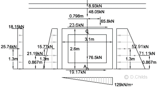
Bearing Pressure under Base at SLS with increased Kmax.
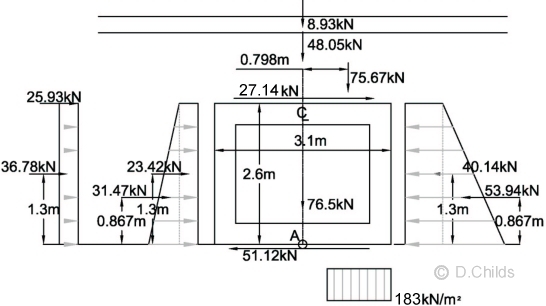
Check for eccentricity of loads at ULS:
Consider EQU bearing pressure under base:
Total vertical load = 8.48 + 45.65 + 65.8 × 1.35 + 72.68 = 215.64kN
Taking moments about the centre of the base (point A in diagram below):
Moment = 2.6 × (27.47 + 31.9) + 1.3 × (38.96 + 19.98 - 27.24) + 0.867 × (26.84 - 36.61) + 88.83 × 0.798 = 257.99kNm
Eccentricity e = M / V = 257.99 / 215.64 = 1.196m.
Check whether eccentricity exceeds base length / 3 = 3.1 / 3 = 1.03 < 1.196m ∴ Fail.
Moment required to limit e to 1.03m = 1.03 × 215.64 = 222.11kNm
Moment from passive forces (using Kmax = 0.6) = 1.3 × 27.24 + 0.867 × 36.61 = 67.15
Kmax required to limit e = 0.6 × (67.15 + 257.99 - 222.11) / 67.15 = 0.92 (< 1.107 for SLS ∴ not critical)
The bearing pressure diagram will be rectangular at ULS so pressure = V / (L - 2e) = 215.64 / (3.1 - 2 × 1.03) = 207.35kN/m2.
Passive force from surcharge = 0.92 × 0.95 ×(2.88 + 15.5) × 2.6 = 41.77kN
Passive force from backfill up to roof = 0.92 × 0.95 × 49.4 × 2.6 / 2 = 56.13kN
Total active force with LM3 traffic = 19.98 + 26.84 + 27.47 + 38.96 + 31.9 = 145.15kN
Total passive force = 41.77 + 56.13 = 97.9kN
Friction force on base to maintain stability = 145.15 - 97.9 = 47.3kN < 123kN ∴ O.K.
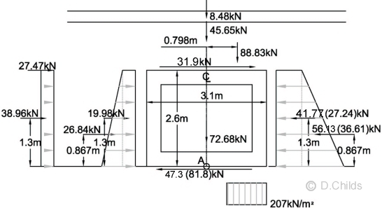
Bearing Pressure under Base at EQU using Kmax = 0.92 (Values in brackets using Kmax = 0.6)
Consider STR/GEO (Comb 1) bearing pressure under base:
Total vertical load = 8.48 + 45.65 + 65.8 × 1.35 + 72.68 = 215.64kN
Taking moments about the centre of the base (point A in diagram below):
Moment = 2.6 × (24.5 + 31.9) + 1.3 × (34.75 + 18.16 - 32.69) + 0.867 × (24.4 - 43.93) + 88.83 × 0.798 = 226.88kNm
Eccentricity e = M / V = 226.88 / 215.64 = 1.05m.
Check whether eccentricity exceeds base length / 3 = 3.1 / 3 = 1.03 < 1.05m ∴ Fail.
Moment required to limit e to 1.03m = 1.03 × 215.64 = 222.11kNm
Moment from passive forces (using Kmax = 0.72) = 1.3 × 32.69 + 0.867 × 43.93 = 80.58
Kmax required to limit e = 0.72 × (80.58 + 226.88 - 222.11) / 80.58 = 0.76 (< 1.107 for SLS ∴ not critical)
The bearing pressure diagram will be rectangular at ULS so pressure = V / (L - 2e) = 215.64 / (3.1 - 2 × 1.03) = 207kN/m2.
Passive force from surcharge = 0.76 × 0.95 ×(2.88 + 15.5) × 2.6 = 34.5kN
Passive force from backfill up to roof = 0.76 × 0.95 × 49.4 × 2.6 / 2 = 46.37kN
Total active force with LM3 traffic = 18.16 + 24.4 + 24.5 + 34.75 + 31.9 = 133.71kN
Total passive force = 34.5 + 46.37 = 80.87kN
Friction force on base to maintain stability = 133.71 - 80.87 = 52.8kN < 135kN ∴ O.K.
Bearing Pressure under Base at STR/GEO (Comb 1) using Kmax = 0.76 (Values in brackets using Kmax = 0.72)
Consider STR/GEO (Comb 2) bearing pressure under base:
Total vertical load = 8.93 + 48.05 + 65.8 × 1.15 + 76.5 = 209.15kN
Taking moments about the centre of the base (point A in diagram below):
Moment = 2.6 × (25.93 + 27.14) + 1.3 × (36.78 + 23.42 - 40.14) + 0.867 × (31.47 - 53.94) + 75.67 × 0.798 = 204.96kNm
Eccentricity e = M / V = 204.96 / 209.15 = 0.98m.
Check whether eccentricity exceeds base length / 3 = 3.1 / 3 = 1.03 > 0.98m ∴ OK.
The bearing pressure diagram will be rectangular at ULS so pressure = V / (L - 2e) = 209.15 / (3.1 - 2 × 0.98) = 183 kN/m2.
Bearing Pressure under Base at STR/GEO (Comb 2) using Kmax = 0.84
Check Bearing Resistance from BS EN 1997-1 Clause D.4
Equation (D.2): R/A' = c'Ncbcscic + q'Nqbqsqiq + 0.5γdB'Nγbγsγiγ
c' = 0 (cohesionless soil)
q' = 1.5 × 19 = 28.5 kN/m2 (overburden pressure)
γ' = 19 kN/m3 (weight density of foundation material)
Nq = eπtanφ'dtan2(45 + φ'd/2)
Nγ = 2 (Nq - 1) tanφ', where δ ≥ φ' / 2 (rough base)
bq = bγ = (1 - αtanφ'd)
Inclination α = 0
sq = 1 + (B' / L') sinφ'd
sγ = 1 - 0.3(B' / L')
m = mB = [2 + (B' / L')] / [1 + (B' / L')] when H acts in the direction of B'
iq = [1 - H / (V + A'c'dcotφ'd)]m
iγ = [1 - H / (V + A'c'dcotφ'd)]m+1
From Figure D.1:
L' = 20.6m (transverse width of foundation)
B = 3.1m B' = B - 2eB
For 1m strip design A' = 1.0 × B' = B'
| SLS | EQU | STR/GEO Comb1 | STR/GEO Comb2 |
|
| eB | 0.517 | 1.03 | 1.03 | 0.98 |
| A' & B' | 3.1 - 2 × 0.517 = 2.066 | 3.1 - 2 × 1.03 = 1.03 | 3.1 - 2 × 1.03 = 1.03 | 3.1 - 2 × 0.98 = 1.14 |
| γd = γ' × γG;inf | 19.0 × 1.0 = 19.0 | 19.0 × 0.95 = 18.05 | 19.0 × 0.95 = 18.05 | 19.0 × 1.0 = 19.0 |
| φ'd | tan-1(tan32 / 1.0) = 32° | tan-1(tan32 / 1.1) = 29.6° | tan-1(tan32 / 1.0) = 32° | tan-1(tan32 / 1.25) = 26.6° |
| Nq | 23.18 | 17.59 | 23.18 | 12.64 |
| Nγ | 27.72 | 18.85 | 27.72 | 11.66 |
| bq & bγ | 1.0 | 1.0 | 1.0 | 1.0 |
| sq | 1.053 | 1.025 | 1.027 | 1.024 |
| sγ | 0.97 | 0.985 | 0.985 | 0.984 |
| m | 1.909 | 1.952 | 1.952 | 1.948 |
| Net Hd | 124.02 - 104.85 = 19.17 | 145.15 - 97.9 = 47.25 | 133.71 - 80.87 = 52.84 | 144.7 - 94.08 = 50.62 |
| Vd | 199.28 | 215.64 | 215.64 | 209.15 |
| iq | 0.821 | 0.612 | 0.574 | 0.582 |
| iγ | 0.74 | 0.476 | 0.432 | 0.441 |
| q'Nqbqsqiq | 571 | 314 | 389 | 214 |
| 0.5γdB'Nγbγsγiγ | 391 | 82 | 110 | 54 |
| R / A' | 962 | 396 | 500 | 269 |
| Vd / A' | 199.28 / 2.066 = 96 | 215.64 / 1.03 = 209 | 215.64 / 1.03 = 209 | 209.15 / 1.14 = 183 |
| R / Vd | 9.98 | 1.90 | 2.39 | 1.46 |
PD 6694-1:2011 Clause 5.2.2 says the serviceability limit state for settlement can be verified by ensuring that a "sufficiently low fraction of the ground strength is mobilized". This requirement can be deemed to be satisfied if the maximum pressure under a foundation at SLS does not exceed one third of the design resistance R/A'.
1/3 (R / A') = 962 / 3 = 321 kN/m2
Maximum bearing pressure at SLS = 129 kN/m2 < 321 ∴ settlement requirement can be deemed to be satisfied.
Minimum Bearing Resistance Factor = 1.46 > 1.0 ∴ O.K.
Kmax had to be increased from the tabulated value for SLS, EQU and STR/GEO (comb.1) Limit States to maintain stability of the structure so we need to ensure that the structure is able to sustain the increased pressures. The plane frame analysis program is used to determine the additional load effects. Minor adjustments to the loading need to be made to minimise the magnitude of the artificial reactions at nodes 1 and 13.
The length of the patch load for the LM3 vehicle will need to be shortened from 1.505m to (1.505 - 2 × 0.15) = 1.205m to keep the load within the limits of the model and also apply the same destabilising moment. Also the bearing pressures will need to be determined using the model base length (2.8m) instead of the structures base length (3.1m).
SLS Moments (Kmax = 1.107)
The loading was entered in the plane frame spreadsheet as a single load case. No allowance was made for the difference in short-term and long-term loading as this will only affect the values of the deflections and not the bending moment, shear and axial effects.
EQU Moments (Kmax = 0.92)
The loading was entered in the plane frame spreadsheet as a single load case. No allowance was made for the difference in short-term and long-term loading as this will only affect the values of the deflections and not the bending moment, shear and axial effects.
STR/GEO Comb. 1 Moments (Kmax = 0.76)
The loading was entered in the plane frame spreadsheet as a single load case. No allowance was made for the difference in short-term and long-term loading as this will only affect the values of the deflections and not the bending moment, shear and axial effects.
Load Case Table B.6
This is similar to Table B.5 loading with the addition of buoyancy effects due to ground water.
Pressures on walls:
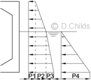
P1 = Surcharge pressure from fill above roof level.
P2 = Backfill pressure from soil above water table.
P3 = Submerged backfill pressure from soil below water table.
P4 = water pressure.
Initial calculations will be based on using Kmax values from Table B.5 for passive earth pressures. Kr values can then be calculated by proportion in order to achieve stability of the structure.
Sliding at SLS:
- γF = 1.0 for all elements.
- Use Kr = 0.6 for initial passive earth pressure coefficient.
- Minimum surcharge from road construction = 0.6 × 4.8 = 2.88kN/m
- Minimum surcharge from fill above roof level = 15.5kN/m
- Active force from surcharge (P1) = 0.33 × (2.88 + 15.5) × 2.6 = 15.77kN
- Passive force from surcharge (P1) = 0.6 × (2.88 + 15.5) × 2.6 = 28.67kN
- Backfill pressure at water table level (P2) = 19 × 1.3 = 24.7kN/m2
- Active force from backfill from water table level up to roof = 0.33 × 24.7 × 1.3 / 2 = 5.30kN
- Active force from backfill surcharge from water table level up to roof = 0.33 × 24.7 × 1.3 = 10.60kN
- Submerged backfill pressure at foundation level (P3) = (19 - 10) × 1.3 = 11.7kN/m2
- Active force from submerged backfill = 0.33 × 11.7 × 1.3 / 2 = 2.51kN
- Active force from ground water (P4) = 10 × 1.3 × 1.3 / 2 = 8.45kN
- Passive force from backfill from water table level up to roof = 0.6 × 24.7 × 1.3 / 2 = 9.63kN
- Passive force from backfill surcharge from water table level up to roof = 0.6 × 24.7 × 1.3 = 19.27kN
- Passive force from submerged backfill = 0.6 × 11.7 × 1.3 / 2 = 4.56kN
- Passive force from ground water (P4) = 10 × 1.3 × 1.3 / 2 = 8.45kN
- Active force from traffic surcharge line load = 0.33 × 55 = 18.15kN
- Active force from LM3 traffic UDL surcharge = 0.33 × 30 × 2.6 = 25.74kN
- Braking and acceleration force for LM3 traffic = 23.6kN
- Total active force with LM3 traffic = 15.77 + 5.30 +10.60 + 2.51 + 8.45 + 18.15 + 25.74 + 23.6 = 110.12kN
- Total passive force = 28.67 + 9.63 + 19.27 + 4.56 + 8.45 = 70.58kN
- Active force > Passive force ∴ friction under the base is required to stop sliding.
- Vertical load on foundation:
- Road construction = 0.6 × 4.8 × 3.1 = 8.93kN
- Fill on roof = 15.5 × 3.1 = 48.05kN
- Self weight of concrete = 76.5kN
- LM3 traffic = 65.8kN
- Buoyancy force = 1.3 × 3.1 × 10 = 40.3kN
- V'd = 8.93 + 48.05 + 76.5 + 65.8 - 40.3 = 158.98kN
- Maximum Rd = 158.98 × tan32° = 99kN
- Friction required = 110.12 - 70.58 = 40 < 99 ∴ sliding can be resisted using Kr = 0.6 ∴ not critical.
Sliding at EQU:
- Use Kr = 0.6 for initial passive earth pressure coefficient.
- Active force from surcharge = 0.44 × 0.95 × (2.88 + 15.5) × 2.6 = 19.98kN
- Passive force from surcharge = 0.6 × 0.95 ×(2.88 + 15.5) × 2.6 = 27.24kN
- Active force from backfill from water table level up to roof = 0.44 × 0.95 × 24.7 × 1.3 / 2 = 6.71kN
- Active force from backfill surcharge from water table level up to roof = 0.44 × 0.95 × 24.7 × 1.3 = 13.42kN
- Active force from submerged backfill = 0.44 × 0.95 × 11.7 × 1.3 / 2 = 3.18kN
- Active force from ground water (P4) = 10 × 0.95 × 1.3 × 1.3 / 2 = 8.03kN
- Passive force from backfill from water table level up to roof = 0.6 × 0.95 × 24.7 × 1.3 / 2 = 9.15kN
- Passive force from backfill surcharge from water table level up to roof = 0.6 × 0.95 × 24.7 × 1.3 = 18.30kN
- Passive force from submerged backfill = 0.6 × 0.95 × 11.7 × 1.3 / 2 = 4.33kN
- Passive force from ground water (P4) = 10 × 0.95 × 1.3 × 1.3 / 2 = 8.03kN
- Active force from traffic surcharge line load = 0.37 × 1.35 × 55 = 27.47kN
- Active force from LM3 traffic UDL surcharge = 0.37 × 1.35 × 30 × 2.6 = 38.96kN
- Braking and acceleration force for LM3 traffic = 1.35 × 23.6 = 31.9kN
- Total active force with LM3 traffic = 19.98 + 6.71 +13.42 + 3.18 + 8.03 + 27.47 + 38.96 + 31.9 = 149.65kN
- Total passive force = 27.24 + 9.15 + 18.3 + 4.33 + 8.03 = 67.05kN
- Active force > Passive force ∴ friction under the base is required to stop sliding.
- Vertical load on foundation:
- Road construction = 0.95 × 8.93 = 8.48kN
- Fill on roof = 0.95 × 48.05 = 45.65kN
- Self weight of concrete = 0.95 × 76.5 = 72.68kN
- LM3 traffic = 1.35 × 65.8 = 88.83kN
- Buoyancy force = 1.3 × 3.1 × 1.05 × 10 = 42.32kN
- V'd = 8.48 + 45.65 + 72.68 + 88.83 - 42.32 = 173.32kN
- Maximum Rd = 173.32 × tan29.6° = 98.46kN
- Friction required = 149.65 - 67.05 = 83 < 98 ∴ sliding can be resisted using Kr = 0.6 ∴ not critical.
Sliding at ULS comb.1:
- Use Kr = 0.72 for initial passive earth pressure coefficient.
- Active force from surcharge = 0.40 × 0.95 × (2.88 + 15.5) × 2.6 = 18.16kN
- Passive force from surcharge = 0.72 × 0.95 ×(2.88 + 15.5) × 2.6 = 32.69kN
- Active force from backfill from water table level up to roof = 0.40 × 0.95 × 24.7 × 1.3 / 2 = 6.10kN
- Active force from backfill surcharge from water table level up to roof = 0.40 × 0.95 × 24.7 × 1.3 = 12.20kN
- Active force from submerged backfill = 0.40 × 0.95 × 11.7 × 1.3 / 2 = 2.89kN
- Active force from ground water (P4) = 10 × 0.95 × 1.3 × 1.3 / 2 = 8.03kN
- Passive force from backfill from water table level up to roof = 0.72 × 0.95 × 24.7 × 1.3 / 2 = 10.98kN
- Passive force from backfill surcharge from water table level up to roof = 0.72 × 0.95 × 24.7 × 1.3 = 21.96kN
- Passive force from submerged backfill = 0.72 × 0.95 × 11.7 × 1.3 / 2 = 5.20kN
- Passive force from ground water (P4) = 10 × 0.95 × 1.3 × 1.3 / 2 = 8.03kN
- Active force from traffic surcharge line load = 0.33 × 1.35 × 55 = 24.50kN
- Active force from LM3 traffic UDL surcharge = 0.33 × 1.35 × 30 × 2.6 = 34.75kN
- Braking and acceleration force for LM3 traffic = 1.35 × 23.6 = 31.9kN
- Total active force with LM3 traffic = 18.16 + 6.1 +12.2 + 2.89 + 8.03 + 24.5 + 34.75 + 31.9 = 138.53kN
- Total passive force = 32.69 + 10.98 + 21.96 + 5.2 + 8.03 = 78.86kN
- Active force > Passive force ∴ friction under the base is required to stop sliding.
- Vertical load on foundation:
- Road construction = 0.95 × 8.93 = 8.48kN
- Fill on roof = 0.95 × 48.05 = 45.65kN
- Self weight of concrete = 0.95 × 76.5 = 72.68kN
- LM3 traffic = 1.35 × 65.8 = 88.83kN
- Buoyancy force = 1.3 × 3.1 × 1.20 × 10 = 48.36kN
- V'd = 8.48 + 45.65 + 72.68 + 88.83 - 48.36 = 167.28kN
- Maximum Rd = 167.28 × tan32° = 104.53kN
- Friction required = 138.53 - 78.86 = 60 < 105 ∴ sliding can be resisted using Kr = 0.72 ∴ not critical.
Sliding at ULS comb.2
- Use Kr = 0.84 for initial passive earth pressure coefficient.
- Active force from surcharge = 0.49 × 1.0 × (2.88 + 15.5) × 2.6 = 23.42kN
- Passive force from surcharge = 0.84 × 1.0 ×(2.88 + 15.5) × 2.6 = 40.14kN
- Active force from backfill from water table level up to roof = 0.49 × 1.0 × 24.7 × 1.3 / 2 = 7.87kN
- Active force from backfill surcharge from water table level up to roof = 0.49 × 1.0 × 24.7 × 1.3 = 15.73kN
- Active force from submerged backfill = 0.49 × 1.0 × 11.7 × 1.3 / 2 = 3.73kN
- Active force from ground water (P4) = 10 × 1.0 × 1.3 × 1.3 / 2 = 8.45kN
- Passive force from backfill from water table level up to roof = 0.84 × 1.0 × 24.7 × 1.3 / 2 = 13.49kN
- Passive force from backfill surcharge from water table level up to roof = 0.84 × 1.0 × 24.7 × 1.3 = 26.97kN
- Passive force from submerged backfill = 0.84 × 1.0 × 11.7 × 1.3 / 2 = 6.39kN
- Passive force from ground water (P4) = 10 × 1.0 × 1.3 × 1.3 / 2 = 8.45kN
- Active force from traffic surcharge line load = 0.41 × 1.15 × 55 = 25.93kN
- Active force from LM3 traffic UDL surcharge = 0.41 × 1.15 × 30 × 2.6 = 36.78kN
- Braking and acceleration force for LM3 traffic = 1.15 × 23.6 = 27.1kN
- Total active force with LM3 traffic = 23.42 + 7.87 + 15.73 + 3.73 + 8.45 + 25.93 + 36.78 + 27.1 = 149.01kN
- Total passive force = 40.14 + 13.49 + 26.97 + 6.39 + 8.45 = 95.44kN
- Active force > Passive force ∴ friction under the base is required to stop sliding.
- Vertical load on foundation:
- Road construction = 1.0 × 8.93 = 8.93kN
- Fill on roof =1.0 × 48.05 = 48.05kN
- Self weight of concrete = 1.0 × 76.5 = 76.5kN
- LM3 traffic = 1.15 × 65.8 = 75.67kN
- Buoyancy force = 1.3 × 3.1 × 1.0 × 10 = 40.3kN
- V'd = 8.93 + 48.05 + 76.5 + 75.67 - 40.3 = 168.85kN
- Maximum Rd = 168.85 × tan26.6° = 84.55kN
- Friction required = 149.01 - 95.44 = 54 < 85 ∴ sliding can be resisted using Kr = 0.84 ∴ not critical.
Overturning:
Stability against overturning is found by considering the eccentricity of loads about the centre of the foundation.
Consider SLS bearing pressure under base:
Total vertical load = 8.93 + 48.05 + 65.8 + 76.5 - 40.3 = 158.98kN
Taking moments about the centre of the base (point A in diagram below):
(Ground water pressures have no net moment about A)
Moment = 2.6 × (18.15 + 23.6) + 1.733 × (5.3 - 9.63) + 1.3 × (25.74 + 15.77 - 28.67) + 0.65 × (10.6 - 19.27) + 0.433 × (2.51 - 4.56) + 65.8 × 0.798 = 163.72kNm
Eccentricity e = M / V = 163.72 / 158.98 = 1.03m.
No uplift will occur if e < base length / 6 = 3.1 / 6 = 0.517 < 1.03m ∴ Fail.
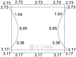
SLS pressures = V/A ± M / Z = 158.98 / (1.0 × 3.1) ± 163.72 / (1.0 × 3.12 / 6) = 51.28 ± 102.22 = 154 and -51 kN/m2.
Bearing Pressure under Base at SLS with Kr = 0.6
Note 3 in Table B.6 says Kmax may be increased to maintain stability, but check movement.
Active moment = 2.6 × (18.15 + 23.6) + 1.733 × 5.3 + 1.3 × (25.74 + 15.77) + 0.65 × 10.6 + 0.433 × 2.51 + 65.8 × 0.798 = 232.16kNm
Passive moment (with Kr = 0.6) = 1.733 × 9.63 + 1.3 × 28.67 + 0.65 × 19.27 + 0.433 × 4.56 = 68.46kNm
To avoid uplift V/A - M/Z > 0
So M < V × Z / A = 158.98 × 3.12 / (6 × 3.1) = 82.14kNm
Passive moment required = 232.16 - 82.14 = 150.02kNm
Maximum bearing pressure = 158.98 / 3.1 + 82.14 × 6 / 3.12 = 103kN/m2
Kr required = 0.6 × 150.02 / 68.46 = 1.315
Revised passive surcharge force = 28.67 × 1.315 / 0.6 = 62.84kN
Revised passive backfill force (P2) = 9.63 × 1.315 / 0.6 = 21.11kN
Revised passive backfill surcharge force (P2) = 19.27 × 1.315 / 0.6 = 42.23kN
Revised submerged passive backfill force (P3) = 4.56 × 1.315 / 0.6 = 9.99kN
Check for movement to develop Kr = 1.32:
From BS EN 1997-1:2004 Figure C.2.1 (with φ' for 6N backfill = 35°) Kp = 3.7
Proportion of Kp required = 1.32 / 3.7 = 0.357 (< 0.5)
PD 6694-1:2011 Clause 7.5 says movement (v/h) varies linearly from zero to v2/h as K increases from K0 to 0.5Kp
0.5Kp = 3.7 / 2 = 1.85
Tables B.1 and B.2 quote K0 as 0.5 at SLS
Proportion of v2/h movement = (1.32 - 0.5) / (1.85 - 0.5) = 0.607
From BS EN 1997-1:2004 Table C.2 for dense soil the range of v2/h for rotational movement = 1.1% to 2.0%
Maximum movement = 2% × 0.607 × 2.6m = 32mm
This movement would need to be checked for impact on adjacent services etc. and be accepted by the approving authority.
For lateral stability under increased passive force:
Active horizontal force = 15.77 + 5.3 + 10.6 + 2.51 + 18.15 + 25.74 + 23.6 + 8.45 = 110.12kN
Passive horizontal force = 62.84 + 21.11 + 42.23 + 9.99 + 8.45 = 144.62kN
Although the passive force is greater than the active force it would still be prudent to check the structure for the increased loading.
Bearing Pressure under Base at SLS with Kr = 1.32.
Check for eccentricity of loads at ULS:
Consider EQU bearing pressure under base:
Total vertical load = 8.48 + 45.65 + 65.8 × 1.35 + 72.68 - 42.32 = 173.32kN
Taking moments about the centre of the base (point A in diagram below):
Moment = 2.6 × (27.47 + 31.9) + 1.733 × (6.71 - 9.15) + 1.3 × (38.96 + 19.98 - 27.24) + 0.65 × (13.42 - 18.3) + 0.433 × (3.18 - 4.33) + 88.83 × 0.798 = 258.56kNm
Eccentricity e = M / V = 258.56 / 173.32 = 1.492m.
Check whether eccentricity exceeds base length / 3 = 3.1 / 3 = 1.03 < 1.492m ∴ Fail.
Moment required to limit e to 1.033m = 1.033 × 173.32 = 179.04kNm
Moment from passive forces (using Kr = 0.6) = 1.733 × 9.15 + 1.3 × 27.24 + 0.65 × 18.3 + 0.433 × 4.33 = 65.04
Kr required to limit e = 0.6 × (65.04 + 258.56 - 179.04) / 65.04 = 1.33 (> 1.32 for SLS ∴ critical)
The bearing pressure diagram will be rectangular at ULS so pressure = V / (L - 2e) = 173.32 / (3.1 - 2 × 1.033) = 167.6kN/m2.
Revised passive force from surcharge = 27.24 × 1.33 / 0.6 = 60.38kN
Revised passive backfill force (P2) = 9.15 × 1.33 / 0.6 = 20.28kN
Revised passive backfill surcharge force (P2) = 18.3 × 1.33 / 0.6 = 40.57kN
Revised submerged passive backfill force (P3) = 4.33 × 1.33 / 0.6 = 9.60kN
Total active force with LM3 traffic = 149.65kN
Total passive force = 60.38 + 20.28 + 40.57 + 9.6 + 8.03 = 138.86kN
Friction force on base to maintain stability = 149.65 - 138.86 = 10.79kN < 98kN ∴ O.K.
Check for movement to develop Kr = 1.33:
From BS EN 1997-1:2004 Figure C.2.1 (with φ' for 6N backfill = 35°) Kp = 3.7
Proportion of Kp required = 1.33 / 3.7 = 0.359 (< 0.5)
PD 6694-1:2011 Clause 7.5 says movement (v/h) varies linearly from zero to v2/h as K increases from K0 to 0.5Kp
0.5Kp = 3.7 / 2 = 1.85
Tables B.1 and B.2 quote K0 as 0.5 at SLS
Proportion of v2/h movement = (1.33 - 0.5) / (1.85 - 0.5) = 0.615
From BS EN 1997-1:2004 Table C.2 for dense soil the range of v2/h for rotational movement = 1.1% to 2.0%
Maximum movement = 2% × 0.615 × 2.6m = 32mm
This movement would need to be checked for impact on adjacent services etc. and be accepted by the approving authority.
The structure will need to assessed for the increased loading.
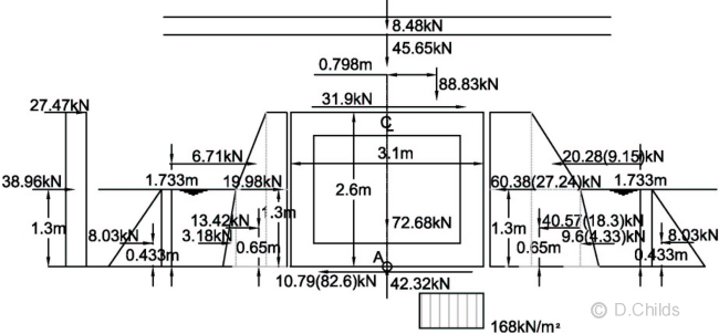
Bearing Pressure under Base at EQU using Kr = 1.33 (Values in brackets using Kr = 0.6)
Consider STR/GEO (Comb 1) bearing pressure under base:
Total vertical load = 8.48 + 45.65 + 65.8 × 1.35 + 72.68 - 48.36 = 167.28kN
Taking moments about the centre of the base (point A in diagram below):
Moment = 2.6 × (24.5 + 31.9) + 1.733 × (6.1 - 10.98) + 1.3 × (34.75 + 18.16 - 32.69) + 0.65 × (12.2 - 21.96) + 0.433 × (2.89 - 5.2) + 88.83 × 0.798 = 228.01kNm
Eccentricity e = M / V = 228.01 / 167.28 = 1.363m.
Check whether eccentricity exceeds base length / 3 = 3.1 / 3 = 1.033 < 1.363m ∴ Fail.
Moment required to limit e to 1.033m = 1.033 × 167.28 = 172.8kNm
Moment from passive forces (using Kr = 0.72) = 1.733 × 10.98 + 1.3 × 32.69 + 0.65 × 21.96 + 0.433 × 5.2 = 78.05
Kr required to limit e = 0.72 × (78.05 + 228.01 - 172.8) / 78.05 = 1.229 (< 1.33 for EQU ∴ not critical)
The bearing pressure diagram will be rectangular at ULS so pressure = V / (L - 2e) = 167.28 / (3.1 - 2 × 1.033) = 161.8kN/m2.
Revised passive force from surcharge = 32.69 × 1.229 / 0.72 = 55.8kN
Revised passive backfill force (P2) = 10.98 × 1.229 / 0.72 = 18.74kN
Revised passive backfill surcharge force (P2) = 21.96 × 1.229 / 0.72 = 37.48kN
Revised submerged passive backfill force (P3) = 5.2 × 1.229 / 0.72 = 8.88kN
Total active force with LM3 traffic = 138.53kN
Total passive force = 55.8 + 18.74 + 37.48 + 8.88 + 8.03 = 128.9kN
Friction force on base to maintain stability = 138.53 - 128.9 = 9.6kN < 105kN ∴ O.K.
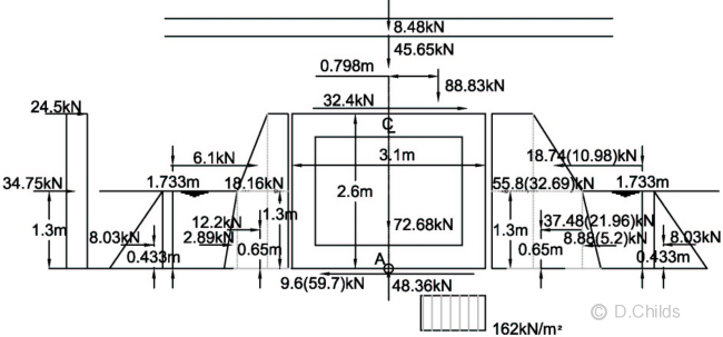
Bearing Pressure under Base at STR/GEO (Comb 1) using Kr = 1.23 (Values in brackets using Kr = 0.72)
Consider STR/GEO (Comb 2) bearing pressure under base:
Total vertical load = 8.93 + 48.05 + 65.8 × 1.15 + 76.5 - 40.3 = 168.85kN
Taking moments about the centre of the base (point A in diagram below):
Moment = 2.6 × (25.93 + 27.1) + 1.733 × (7.87 - 13.49) + 1.3 × (36.78 + 23.42 - 40.14) + 0.65 × (15.73 - 26.97) + 0.433 × (3.73 - 6.39) + 75.67 × 0.798 = 206.14kNm
Eccentricity e = M / V = 206.14 / 168.85 = 1.22m.
Check whether eccentricity exceeds base length / 3 = 3.1 / 3 = 1.033 < 1.22m ∴ Fail.
Moment required to limit e to 1.033m = 1.033 × 168.85 = 174.42kNm
Moment from passive forces (using Kr = 0.84) = 1.733 × 13.49 + 1.3 × 40.14 + 0.65 × 26.97 + 0.433 × 6.39 = 95.86
Kr required to limit e = 0.84 × (95.86 + 206.14 - 174.42) / 95.86 = 1.118 (< 1.33 for EQU ∴ not critical)
The bearing pressure diagram will be rectangular at ULS so pressure = V / (L - 2e) = 168.85 / (3.1 - 2 × 1.033) = 163.3kN/m2.
Revised passive force from surcharge = 40.14 × 1.118 / 0.84 = 53.42kN
Revised passive backfill force (P2) = 13.49 × 1.118 / 0.84 = 17.95kN
Revised passive backfill surcharge force (P2) = 26.97 × 1.118 / 0.84 = 35.9kN
Revised submerged passive backfill force (P3) = 6.39 × 1.118 / 0.84 = 8.5kN
Total active force with LM3 traffic = 149.01kN
Total passive force = 53.42 + 17.95 + 35.9 + 8.5 + 8.45 = 124.22kN
Friction force on base to maintain stability = 149.01 - 124.22 = 24.79kN < 85kN ∴ O.K.
Bearing Pressure under Base at STR/GEO (Comb 2) using Kr = 1.12 (Values in brackets using Kr = 0.84)
Check Bearing Resistance from BS EN 1997-1 Clause D.4
Equation (D.2): R/A' = c'Ncbcscic + q'Nqbqsqiq + 0.5γdB'Nγbγsγiγ
c' = 0 (cohesionless soil)
q' = 1.5 × 19 = 28.5 kN/m2 (overburden pressure)
γ' = 19 kN/m3 (weight density of foundation material)
Nq = eπtanφ'dtan2(45 + φ'd/2)
Nγ = 2 (Nq - 1) tanφ', where δ ≥ φ' / 2 (rough base)
bq = bγ = (1 - αtanφ'd)
Inclination α = 0
sq = 1 + (B' / L') sinφ'd
sγ = 1 - 0.3(B' / L')
m = mB = [2 + (B' / L')] / [1 + (B' / L')] when H acts in the direction of B'
iq = [1 - H / (V + A'c'dcotφ'd)]m
iγ = [1 - H / (V + A'c'dcotφ'd)]m+1
From Figure D.1:
L' = 20.6m (transverse width of foundation)
B = 3.1m B' = B - 2eB
For 1m strip design A' = 1.0 × B' = B'
| SLS | EQU | STR/GEO Comb1 | STR/GEO Comb2 |
|
| eB | 0.517 | 1.033 | 1.033 | 1.033 |
| A' & B' | 3.1 - 2 × 0.517 = 2.067 | 3.1 - 2 × 1.033 = 1.033 | 3.1 - 2 × 1.033 = 1.033 | 3.1 - 2 × 1.033 = 1.033 |
| γd = γ' × γG;sup | 19.0 × 1.0 = 19.0 | 19.0 × 0.95 = 18.05 | 19.0 × 0.95 = 18.05 | 19.0 × 1.0 = 19.0 |
| φ'd | tan-1(tan32 / 1.0) = 32° | tan-1(tan32 / 1.1) = 29.6° | tan-1(tan32 / 1.0) = 32° | tan-1(tan32 / 1.25) = 26.6° |
| Nq | 23.18 | 17.59 | 23.18 | 12.64 |
| Nγ | 27.72 | 18.85 | 27.72 | 11.66 |
| bq & bγ | 1.0 | 1.0 | 1.0 | 1.0 |
| sq | 1.053 | 1.025 | 1.027 | 1.023 |
| sγ | 0.97 | 0.985 | 0.985 | 0.985 |
| m | 1.909 | 1.952 | 1.952 | 1.952 |
| Net Hd | 144.62 - 110.12 = 34.5 | 149.65 - 138.86 = 10.79 | 138.53 - 128.9 = 9.63 | 149.01 - 124.22 = 24.79 |
| Vd | 158.98 | 173.32 | 167.28 | 168.85 |
| iq | 0.627 | 0.889 | 0.895 | 0.733 |
| iγ | 0.491 | 0.837 | 0.845 | 0.626 |
| q'Nqbqsqiq | 436 | 457 | 607 | 269 |
| 0.5γdB'Nγbγsγiγ | 259 | 144 | 215 | 70 |
| R / A' | 695 | 601 | 822 | 339 |
| Vd / A' | 158.98 / 2.066 = 77 | 173.32 / 1.033 = 168 | 167.28 / 1.033 = 162 | 168.85 / 1.033 = 163 |
| R / Vd | 9.04 | 3.59 | 5.08 | 2.08 |
PD 6694-1:2011 Clause 5.2.2 says the serviceability limit state for settlement can be verified by ensuring that a "sufficiently low fraction of the ground strength is mobilized". This requirement can be deemed to be satisfied if the maximum pressure under a foundation at SLS does not exceed one third of the design resistance R/A'.
1/3 (R / A') = 695 / 3 = 233 kN/m2
Maximum bearing pressure at SLS = 103 kN/m2 < 233 ∴ settlement requirement can be deemed to be satisfied.
Minimum Bearing Resistance Factor = 2.08 > 1.0 ∴ O.K.
Kr had to be increased from the tabulated Kmax values for all Limit States to maintain stability of the structure so we need to ensure that the structure is able to sustain the increased pressures. The plane frame analysis program is used to determine the additional load effects. Minor adjustments to the bearing pressures need to be made to minimise the magnitude of the artificial reactions at nodes 1 and 13.
SLS Moments (Kr = 1.32)
The loading was entered in the plane frame spreadsheet as a single load case. No allowance was made for the difference in short-term and long-term loading as this will only affect the values of the deflections and not the bending moment, shear and axial effects.
EQU Moments (Kr = 1.33)
The loading was entered in the plane frame spreadsheet as a single load case. No allowance was made for the difference in short-term and long-term loading as this will only affect the values of the deflections and not the bending moment, shear and axial effects.
STR/GEO Comb. 1 Moments (Kr = 1.23)
The loading was entered in the plane frame spreadsheet as a single load case. No allowance was made for the difference in short-term and long-term loading as this will only affect the values of the deflections and not the bending moment, shear and axial effects.
STR/GEO Comb. 2 Moments (Kr = 1.12)
The loading was entered in the plane frame spreadsheet as a single load case. No allowance was made for the difference in short-term and long-term loading as this will only affect the values of the deflections and not the bending moment, shear and axial effects.
Reinforcement Design
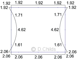
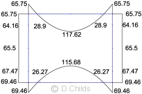
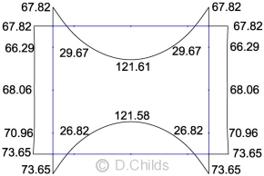
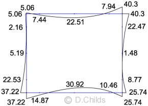
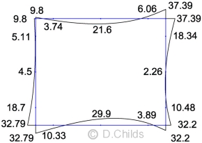
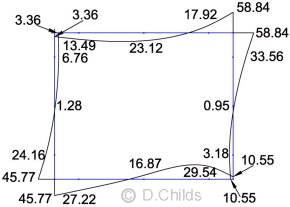
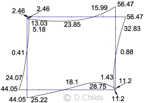
Taking the maximum moments from the results of loading tables B.1 to B.6, and assuming all loading can be mirrored, an envelope is produced. Values shown in black are for moments which produce tension on the outside face whilst values in red are for tension of the inside face of the culvert. Only half the values are shown for clarity; the values are mirrored about the vertical axis.
Envelope of SLS Moments
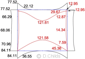
Envelope of ULS Moments
Use C32/40 concrete to BS 8500.
Use Grade B500B reinforcement to BS 4449.
BS 8500-1
cl. A.2.1 Table A.1: Assume exposure Class XD2.
cl. A.3: Fixing tolerance for reinforcement Δc = 15mm for insitu concrete.
Table A.5: Nominal cover for C32/40 concrete = 45 + Δc = 60mm with
maximum water-cement ratio = 0.50 and minimum cement content of 340 kg/m3.
EN 1992-2
The reinforcement requirements can be determined by following the procedure in the 'Reinforced Concrete Deck' example or by using a simple spreadsheet.
Maximum shear and axial loads are obtained in a similar process to the moments.
Critical shear positions are located at d away from the face of the support. Nodes 2, 4, 6, 8, 10, 12, 14 and 16 were located in the plane frame model to obtain these values. Maximum shear values obtained were:
- Nodes 2 & 12 = 55kN
- Nodes 4 & 10 = 61kN
- Nodes 6 & 8 = 191kN
- Nodes 14 & 16 = 202kN
All axial values were compressive with the exception of one load case with maximum water level inside the culvert which produced a tension of 1.4kN in the floor slab. Maximum axial values obtained were:
- Walls = 262kN at top to 281kN at bottom
- Roof = 102kN
- Floor = 84kN
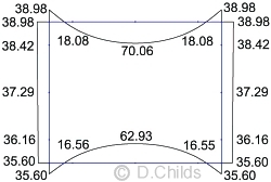
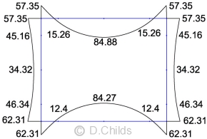
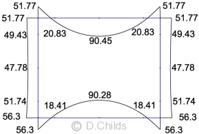
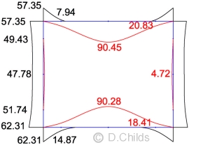
Maximum moments are at mid-span in the roof and floor; these were produced in Table B.3 loading. SLS moments need to be specified in terms of effects from quasi-permanent and short-term actions.
The SLS mid-span roof moment of 90.45kNm consists of 20.39kNm quasi-permanent loading and 70.06kNm short-term loading (load case D7).
The SLS mid-span floor moment of 90.28kNm consists of 27.35kNm quasi-permanent loading and 62.93kNm short-term loading (load case D7).
Mqp / Mst is 0.291 for the roof moment and 0.435 for the floor moment.
Using spreadsheet 304 suitable reinforcement for a 300mm thick slab is 16mm dia. reinforcement at 125mm centres (Mult = 148kNm > 121.6kNm, Msls for characteristic combinations = 118kNm > 90.45kNm, Msls for quasi-permanent combinations = 82kNm > 27.35kNm).
All sections in the structure can be designed for bending in a similar way.
Shear
Shear is considered at a distance d away from the support. Nodes on the plane frame model were positioned at these points.
Worst shear in floor slab at nodes 14 and 16 is 202kN
Spreadsheet 304 shows 16mm dia. reinforcement at 125mm centres (As = 1608mm2/m) has a shear resistance of 302kN at distance d away from the support.
As the critical sections (d from support) are close to points of contraflexure then tension can occur both on the inside and outside faces of the structure. The longitudinal tensile steel to resist shear should therefore be provided on both faces.
Shear resistance in the walls can be checked using EN 1992-1-1 Clause 6.2.2 equation 6.2a:
VRd,c = [CRd,ck(100 ρ1 fck)1/3 + k1 σcp] bwd
Minimum axial compressive load NEd in wall at critical shear nodes 4 & 10 (load case table B.2 ULS Comb.1) = 39.75kN
Ac = 1000 × 300 = 300 × 103mm2
σcp = NEd / Ac < 0.2 fcd
σcp = 39.75 / 300 = 0.133 N/mm2
fcd = 18.133N/mm2 (from spreadsheet 304)
0.2 fcd = 0.2 × 18.133 = 3.627 > 0.133 ∴ OK
Try using B12@125 then
d = 300 - 60 - 12 / 2 = 234
k1 = 0.15 from UK NA to BS EN 1992-1-1 Table NA.1
k1 σcp bwd = 0.15 × 0.133 × 1000 × 234 / 1000 = 4.7kN
Maximum ULS moment in wall at nodes 2 and 12 = 70.96kNm
Using spreadsheet 304 to check the capacity of B12@125c/c (ULS moment capacity = 88kNm > 70.96) then the shear capacity at d from support taking account of the axial effects = 2 × (124.99 + 4.7) = 259.38kN > 61kN ∴ OK.
It should be noted that the minimum axial (Table B.2 comb.1) and shear (Table B.6 EQU) effects are not co-existing, however the calculation does show the reinforcement will be adequate. Not using co-existing values can lead to over designing the section and hence an uneconomical solution.
All sections in the structure can be designed for shear and axial effects in a similar way.
As there are no joints in the structure then it is important to check for early thermal crack control considering:
- The floor slab being cast onto blinding
- The walls being cast onto the floor slab
- The roof slab being cast onto the walls
This can be achieved by using spreadsheet 306.
Back to Buried Box Tutorial | Back to Tutorial Index
Contact David Childs

David Childs
B.Sc, C.Eng, MICE
Last Updated: 17/04/2020