
Buried Box Design to PD 6694-1:2011
(Eurocode to UK Standard)
Index
1. Materials & Construction
PD 6694-1 'Recommendations for the design of structures subject to traffic loading to BS EN 1:2004' Clauses 9.10.1 and 10.2.3 give requirements for the materials and construction for buried concrete box structures. These structures include in-situ or precast culverts and underpasses.
The construction of the box structure will have implications on the design which need to be considered.
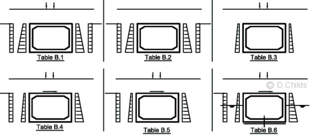
Although vertical drainage layers are required to be provided for underpasses ground water levels and the possibility of buoyancy effects needs to be considered as described in load case Table B.6. The drainage layer separates the backfill soil from the walls of the box however the back of wall friction is deemed to be included in the tabulated coefficients in the tables.
Preparation of the foundation for the box is important to ensure the structure is evenly supported. The definition of the existing ground material below the box is either 'hard' or 'not hard'; 'hard material' being defined as material which requires the use of blasting, breakers or splitters for its removal. The diagram above shows how either blinding concrete or granular material needs to be placed below the structure to achieve a uniform bedding layer.
Backfill to the structure is restricted to Class 6N or 6P material as defined in the Manual of Contract Documents for Highway Works Volume 1 Specification Series 600 Clause 610 and Table 6/1.
Coefficients of earth pressure for Class 6N and 6P material used in Tables B.1 to B.6 at Serviceability Limit State are:
Ka = 0.33 which equates to a ϕ' value of 30°
Ko for soil pressure = 0.6 which equates to a ϕ' value of 23.6°
Ko for traffic surcharge = 0.5 which equates to a ϕ' value of 30°
In Table B.3 a minimum value for K is given as 0.2 to consider the minimum earth pressure effects when the roof structure is heavily loaded with traffic.
The value of Kmax in the Tables may be increased when considering bearing pressures, overturning or sliding providing the structure is designed for the increased pressures, and the movement required to develop the passive resistance can be accommodated (see Clauses 10.3.2 and 10.3.3).
2. Loading
Permanent loading comprises of the self-weight of the box, the weight of the carriageway construction and fill over the box, horizontal earth pressures from the backfill material, hydrostatic pressures from ground water, and settlement.
Both the minimum and maximum values of permanent loads need to be considered to assess the worst effects in the structure. The weight of the material over the box acting on the roof slab can be enhanced by the effect of negative arching.
Negative Arching
Negative arching effects are caused by consolidation or settlement of the fill either side of the structure. This effect increases the load from the fill over the roof slab. A model factor γSd;ec is applied to the weight of fill and surfacing over the structure to take account of negative arching effects. The scope of the Standard limits designs up to a maximum of 11m fill depth above the roof slab.
Horizontal earth pressures can vary considerably, the range of values for the earth pressure coefficients, together with appropriate combination load factors are shown below Tables B.1 to B.6 in Annex B.
Live Loads consist of traffic loading (LM1, LM2 and LM3), footway loading, accidental wheel loading, construction traffic, traction and skidding loads, parapet collision loads, centrifugal loads and temperature effects. Although the list is extensive all the items need to be considered, however some may be discounted by observation.
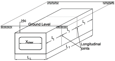
Dimension Notation
Temperature Effects may be neglected when cover Hc > 0.6m and LT > 5 × Xclear.
Note: Precast units within 1.25 × Xclear from the edge of the structure need to be considered for temperature effects.
Temperature Difference effects may be neglected when cover Hc > 0.5m.
Uniform Temperature effects may be neglected when cover Hc ≥ 1.5m.
If the cover Hc is greater than LL then braking and acceleration forces may be neglected.
Note: the scope of the Standard limits designs to structures with the length LL ≤ 15.0m.
When cover Hc is 0.6m or less then three vertical live loads need to be considered:
- Load Model 1 (LM1).
There is no dispersal allowed for the UDL System so the nominal UDL = 5.5 kN/m2. Wheel loads for the Tandem System are applied uniformly over a contact area of 0.4m × 0.4m; this contact pressure may be dispersed at 1:11 through the surfacing and fill and concrete to the neutral axis of the roof slab in accordance with BS EN 1991-2 Clause 4.3.6. - Load Model 2 (LM2).
Wheel loads for the single axle are applied uniformly over a contact area of 0.4m × 0.4m; this contact pressure may be dispersed at 1:11 through the surfacing and fill and concrete to the neutral axis of the roof slab in accordance with BS EN 1991-2 Clause 4.3.6. - Load Model 3 (LM3).
The value of the SV model vehicle used will depend on the class of road over the box structure. Wheel loads for the SV vehicle are applied uniformly over a contact area of 0.35m × 0.35m; this contact pressure may be dispersed at 1:11 through the surfacing and fill and concrete to the neutral axis of the roof slab in accordance with BS EN 1991-2 Clause 4.3.6.
Note 1: A dispersal of 1:1 does lead to an anomaly when considering load dispersal for Hc greater than 0.6m as loads are then dispersed at an angle of 30° to the vertical. This results in traffic loading having a worse effect on fill depths of between 0.6m and about 1m than those on a depth of 0.6m. It is recommended that dispersal is considered at 30° to the vertical for all depths of cover Hc.
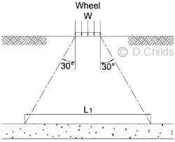
Wheel load remote from vertical walls.
When cover Hc is greater than 0.6m then the wheel contact pressures are dispersed from the road level down to the top of the box roof at an angle of 30° to the vertical. The load is dispersed longitudinally and transversely over a distance L1.
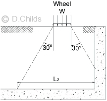
Wheel load near vertical walls.
When the wheel is near to a vertical wall, such as a wing wall or head wall, and the 30° dispersal is curtailed by the wall then the load is dispersed over the reduced length L2. The dispersed area on top of the box will be L1 × L2.
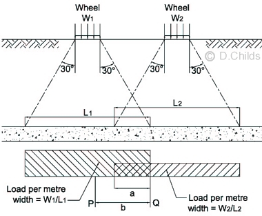
Two dispersion zones overlap.
When the depth of fill Hc is such that the dispersal zones on adjacent wheels overlap then the maximum loading on a unit strip (width b) is taken as bW1/L1 + aW2/L2 where W1 is the larger wheel load and 'a' is the length overlap.
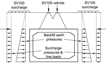
Traffic surcharge represents vehicles positioned adjacent to the box structure and is applied as a uniformly distributed load together with two horizontal line loads to the side of the box.
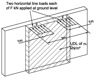
Horizontal Surcharge Model.
When considering a unit strip method the horizontal line load F = 330KdDf. Two line loads are applied so for a 3m lane width the load on a 1m wide strip = 2 × 330KdDf/3 = 220KdDf.
Kd is Ka or K0 and is obtained from the appropriate load case Table in Annex B.
Df is a reduction factor for the distribution effect down the wall. It is safe to initially assume a value of 1 for the analysis and consider applying the factor for sections near the floor slab if design values are onerous.
Values for the UDL σh depend on the traffic load model being considered.
For Normal Traffic (LM1 or LM2): σh = 20KdR
For LM3 (SV's): σh = 30KdR
For Abnormal Loads (SOV's): σh = 45KdR
Where R is 3.0/Weff;, so for a 3m lane width R = 1.0.
The UDL surcharge and line loads are applied in conjunction with the vertical live load vehicle over the roof slab in Tables B.1, and B.4 to B.6. The magnitude of the surcharge relates to the vertical live load vehicle over the box and, for example, does not represent the frequent value of LM1 in the case of Group gr5 traffic loading. Table B.2 represents the case with surcharge applied to the sides of the box with no vertical live load over the box, whilst Table B.3 has no surcharge but vertical live load over the roof only.
Example of HB live loading
Load Case Combinations to be considered:
Temperature Effects need to be considered when the depth of fill over the structure is shallow, or when the maximum clear span is more than 20% of the width LT of the structure. The two effects that need to be analysed are:
- Uniform Temperature.
This is the expansion and contraction effect of the roof slab. A mid-range temperature of 10° is assumed with expansion up to Tmax and contraction down to Tmin. Where Tmax and Tmin are determined from BS EN 1991-1-5 and UK NA and are adjusted for the depth of cover using NA to BS EN 1991-1-5 Clause NA.2.2.2.
Uniform Temperature Effects - Temperature Difference.
This occurs when there is a temperature gradient through the roof slab, i.e. when there is a different temperature on the top of the slab to that on the soffit. NA to BS EN 1991-1-5 Clause NA.2.2.3 is used to determine the effects of temperature difference. The restraining moments and forces need to be distributed into the structure, and the self-equilibrating stresses added into the load effects in the roof member.
3.Stability
Stability of the box is considered in Tables B.4 to B.6 where horizontal live loads, such as traction forces, are applied to the top of the roof slab. Stability is maintained by either increasing the horizontal earth pressures on the opposite side of the box, or considering friction forces on the base of the box, or a combination of the two effects.
Sliding effects are considered in Table B.6. The out-of-balance horizontal force is resisted by friction under the base of the box and passive resistance of the soil on the side of the box. The earth pressure coefficient for the passive wall may be taken as greater than Kmax for bearing, sliding and overturning.
Passive pressures can only be developed when the structure moves (lateral and/or rotational displacements). The movement required to develop full passive pressure can be significant. The magnitude of movement can be determined using PD 6694-1 Clause 7.5 and care is needed to check that the structure and surrounding services (such as gas mains and drainage systems) can accommodate the movement.
Allowable bearing pressures are obtained from the Ground Investigation Survey. An allowable pressure is usually determined to limit differential settlement to about 20 to 25mm.
4.Analysis
A unit strip method of analysis is usually suitable for most box designs.
A simple plane frame model will usually be suitable for modelling the distribution effects of the loads around the structure. Alternatively a moment distribution analysis can be used effectively.
Moments and shears are determined at critical points around the structure, i.e at corners and mid lengths of walls, roof and floor slabs. The critical section for shear in the slabs is at distance d from the end of the splay, or the corner when there is no splay, as shown.
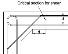
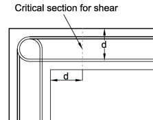
It is important to check for combined bending and shear at these critical sections.
Special attention to reinforcement detailing is required when bending causes tension on the inside of the box at the corners. BS EN 1992-1-1 Clause J.2.3 describes strut and tie models for use in determining reinforcement requirements at corners with opening moments. Appendix D of BD 31/01 describes a method of designing for these corner 'opening' moments. An example of the calculation has been provided in the Workshop Section of this website.
Design Example to PD 6694 | Back to Tutorial Index
Contact David Childs

David Childs
B.Sc, C.Eng, MICE
Last Updated: 28/01/2020